SV-D700, SV-D1000 and SV-D1000T Operation
SkyView Classic Pilot’s User Guide –
Revision Z
4-17
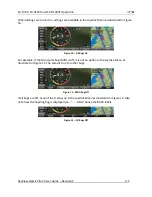
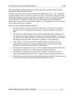
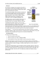
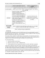
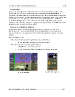
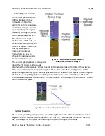
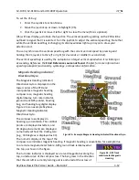
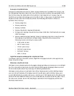
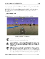
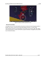
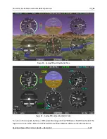
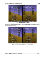
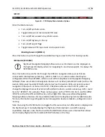
HSI Info Items
Figure 35
-
HSI GPS Info
Figure 36
-
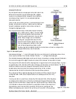
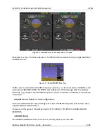
HSI NAV Info
(LOC Example)
Figure 37
-
Virtual DME
Figure 38
-
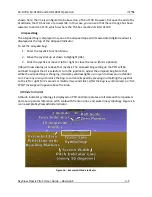
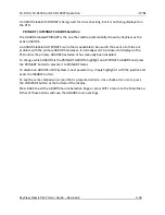
OBS Mode
Active
Textual info items that provide additional data about the HSI source are displayed to the right
of the HSI display. The information available depends on the data being provided by the HSI
source. Examples of info items that may be displayed include DTW (distance to waypoint), ID
(VOR identifier), and frequency. When a NAV radio decodes the identifier for a frequency,
SkyView displays it in the HSI info area and tries to match the identifier to the same one in its
aviation database. When it finds a match, it displays Virtual-DME (non-certified) distance in
magenta. Note that ARINC-connected devices like the 430/GTN do not decode identifiers, and
therefore SkyView cannot calculate Virtual-DME for those radios.
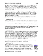
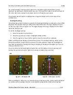
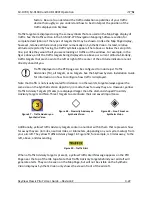
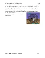
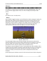
Wind Vector
Wind vector information is located just above the OAT display on the PFD. The
winds aloft arrow indicates the wind direction relative to your current direction of
flight. The wind strength, direction, and cross wind component are also textually
provided. If SkyView cannot make an accurate winds aloft calculation, the arrow is not
displayed and the numbers are replaced by dashes. The display of winds aloft requires an
active GPS connection and an OAT probe. In very light winds, the wind speed number is not
displayed, although the arrow is. Note that due to a limitation in the SV-GPS-250 hardware,
winds information will not be available above 415 knots ground speed if it is being used as the
GPS source. The Wind Vector will not appear if the SV-ADAHRS-20X, SV-MAG-236, GPS, or OAT
is not functional.
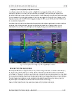
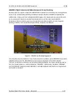
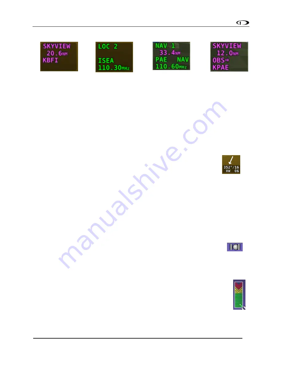
Slip/Skid Ball
The action of the slip/skid ball simulates an analog slip/skid ball and provides a
visual representation of lateral acceleration. When the ball is within the two
vertical lines, the aircraft is in coordinated flight. Figure 40 is an example
SkyView slip/skid ball.
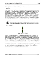
Angle of Attack Indicator
The Angle Of Attack (AOA) Indicator will display only when a Dynon AOA/Pitot probe
has been properly installed and calibrated. During normal flight, the AOA Indicator will
display green. As the AOA approaches and then reaches critical, the green and yellow
bars will disappear, leaving only red. Figure 41 is an example SkyView AOA
indicator.
Figure 40
–
Example
Slip/Skid Ball
Figure 41
–
Example AOA
Indicator
Figure 39
-
Wind Vector

