background image

1.  Benutzerinformationen


1.1Wichtige Sicherheitsanweisungen  ..................................................3


1.2Wichtige Anweisungen f. sichere Montage......................................3


1.3Sicherheitsbestimmungen und -vorschriften ..................................4

2.  Zubehör und optionales Zubehör ........................................................5
3.  Funktionen und Vorteile


3.1Geeignete Tortypen ............................................................................6


3.2Funktionen ...........................................................................................7

4.  Benötigte Werkzeuge u. Hilfsmittel ....................................................7
5.  Vormontage / Zusammenbau


5.1Zusammenbau von Führungsschiene und Transportschlitten........8 


5.2Gerade bzw. gebogene Zug-/Schubstange montieren...................8


5.3Kette positionieren und befestigen...................................................9


5.4Kette spannen .....................................................................................9


5.5Führungsschiene am Antriebskopf befestigen................................10

6

.

  Montage Antriebseinheit mit Garagentor


6.1Position für Kopfwandlager ermitteln ...............................................10


6.2Kopfwandlager montieren..................................................................11


6.3Führungsschiene an Kopfwandlager montieren .............................12-13


6.4Antrieb positionieren und montieren ................................................13-16


6.5Torlager für Zug-/Schubstange montieren.......................................16-18


6.6Zug-/Schubstange an Transportschlitten montieren......................18-21


6.7Lichtschranke installieren (optional)................................................22


6.8Antrieb an Spannungsversorgung anschließen..............................23

7

.

  Einstellungen am Antrieb


7.1Einleitung/Sicherheitshinweise ........................................................23


7.2Erläuterungen zum Bedienfeld und der Symbole ...........................24


7.3Endpunkt für das Öffnen einstellen ..................................................24


7.4Endpunkt für das Schließen einstellen.............................................25


7.5Einstellen der Kraft für das Öffnen und Schließen..........................25-26


7.6Testen der Hinderniserkennung........................................................27


7.7Funktionstest der Lichtschranke (optional).....................................28

8. Funktion zum automatischen Schließen des Tores...................................        29 
9. Programmierung


9.1 Programmierung Fernbedienung.....................................................29


9.2 Tauschen der Batterien bei den Sendern ........................................29


9.3 Programmierung des Keypad-Funksenders...................................30f

10

.

 Sendercodes löschen ............................................................................34

11

.

 Bedienung der Notentriegelung ..........................................................35

12

.

 Fehlersuche / -behebung.......................................................................36

13

.

 Garantie .....................................................................................................37

14

.

 Optionaler Zubehör.................................................................................38

15

.

 Techn. Daten ............................................................................................39

Im Servicefall wenden Sie sich bitte an Ihren Händler.
Gerne helfen auch wir weiter. Schreiben Sie uns unter heicko@verkauf.de

heicko e-ast gmbh
Käthe-Kollwitz-Straße 15
D-51545 Waldbröl

© heicko 2015 – 

Vervielfältigung und Nachdruck nur mit unserer Genehmigung

2

Summary of Contents for 1000NM1

Page 1: ...eb Garage door opener Moteur pour portes de garage 800NM1 1000NM1 heicko e ast gmbH K the Kollwitz Stra e 15 51545 Waldbr l www heicko de Bedienungsanleitung deutsch User manual english Manuel d utili...

Page 2: ...Montage und Bedienungsanleitung Garagentorantriebe mit Kettenantrieb f r Schwing und Sektionaltore 800NM1 und 1000NM1 GT10 04_D...

Page 3: ...en 18 21 6 7Lichtschranke installieren optional 22 6 8Antrieb an Spannungsversorgung anschlie en 23 7 Einstellungen am Antrieb 7 1Einleitung Sicherheitshinweise 23 7 2Erl uterungen zum Bedienfeld und...

Page 4: ...eiten erforderlich sind Ein nicht korrekt ausbalanciertes Tor oder Fehler in der gesamten Anlage k nnen Verletzungen Verursachen F hren Sie keine Ver nderungs oder und Reparaturarbeiten am Tor durch u...

Page 5: ...ufsichtigt oder in das sichere Bedienen des Torantriebes unterwiesen wurden und dadurch m gliche Gefahren verstehen und erkennen 1 3 Wichtige Sicherheitsbestimmungen und Vorschriften Ortsfest installi...

Page 6: ...2 Zubeh r und optionales Zubeh r Nicht im Lieferumfang Nicht im Lieferumfang Nicht im Lieferumfang 5...

Page 7: ...tionen und Vorteile 3 1 Geeignete Garagen Tortypen Dieser Garagentorantrieb ist f r Schwing und Sektionaltore im Wohnbereich vorgesehen Sektionaltor Maximale H he 2 13 m Schwingtor Maximale H he 2 23...

Page 8: ...fen auf ein Hindernis Griff zur Notentriegelung Integrierte Beleuchtung f r Sicht bei Dunkelheit schaltet sich automatisch ein wenn Antrieb aktiviert wird und automatisch aus nach ca 4 Min 4 Werkzeuge...

Page 9: ...enenteile zusammen montieren den Schlitten und den Hebel f r die Notentriegelung VORSICHT Verletzungsgefahr durch Einklemmen Halten Sie Finger m glichst von den F gestellen der Schienenteile fern 5 2...

Page 10: ...er Motorseite der Schiene 5 4 Spannen der Kette Die Spannvorrichtung f r die Kette befindet sich auf der Torseite der Schiene Hinweis Vor sp teren Wartungsarbeiten an der Kette ist immer mit der Noten...

Page 11: ...Der Zusammenbau von Schiene und Antrieb ist jetzt abgeschlossen 6 Montage Wichtige Hinweise zur Montage Befolgen Sie die Sicherheitsanweisungen unter 1 Benutzerinformationen auf Seite 3 f Tragen Sie u...

Page 12: ...finden Bringen Sie das Label f r die Notentriegelung im sichtbaren Bereich in der N he des Tores oder Antriebes an 6 1 Position f r Kopfhalterung festlegen Kopfwand Vertikale Mitte des Garagentors Hil...

Page 13: ...Decke nicht m glich so muss eine Hilfskonstruktion zur Befestigung erstellt werden Bei Befestigung in Mauerwerk oder Beton m ssen geeignete D bel verwendet werden D bel sind im Lieferumfang nicht ent...

Page 14: ...ng 6 3 Befestigen Sie die Schiene an dem Kopfwandlager Schiebe Sie die Schiene mit dem Gabelkopfende in die Kopfhalterung Fixieren Sie die Schiene mit dem Bolzen 17 an der Kopfhalterung und sichern de...

Page 15: ...en Achtung Um Sch den an Garagentor Schiene und Antrieb zu vermeiden nehmen Sie bitte eine 2 Person zur Hilfe Schritt 1 Befestigen Sie die U B gel 5 auf der Schiene und verbinden das kurze Winkelstahl...

Page 16: ...s Winkelprofils bis zur Decke Schneiden Sie die zwei langen Winkelstahlprofile 12 entsprechend und verbinden diese mit dem kurzen Winkelprofil an der Schiene sowie dem zweiten kurzen Winkelprofil Zum...

Page 17: ...der Antrieb mit der Schiene mit geeigneten Verbindungsmitteln an der Decke dauerhaft befestigt ist Es muss gew hrleistet sein dass die Befestigungsstellen den Antrieb mit der Schiene dauerhaft tragen...

Page 18: ...ng geeignet ist Bitte kontaktieren Sie dazu den Torhersteller und beschaffen sich ber diesen ggf Elemente zur Verst rkung A Sektionaltore Schritt 1 Nutzen sie hierzu die bereits markierte vertikale Mi...

Page 19: ...ositionieren Sie den oberen Rand des Torlagers 5 10 cm unterhalb der Oberkante des Tores Schritt 3 Markieren Sie die Stellen f r die Bohrl cher bohren die L cher und montieren das Torlager mit der Sch...

Page 20: ...Folgen Sie den zutreffenden Anweisungen A Sektionaltore Schritt 1 Schlie en Sie das Tor Trennen Sie den Transportschlitten durch Ausl sen der Notentriegelung Schritt 2 Befestigen Sie die gebogene Zug...

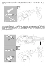
Page 21: ...nach baulicher Gegebenheit kann es erforderlich sein dass die gerade Zug Schubstange als Verl ngerung an die gebogene Zug Schubstange montiert werden muss siehe folgende Abb und verwenden Sie die Schr...

Page 22: ...en Sie die gerade Zug Schubstange am Torlager f r die Stange mit dem Sicherungsbolzen und sichern diesen mit dem Sicherungsclip Schritt 3 Befestigen Sie die gebogene Zug Schubstange an dem Transportsc...

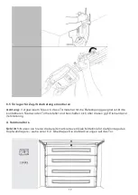
Page 23: ...all m ssen alle Montageschritte auf eventuelle Fehler berpr ft werden Achtung Montagefehler sind unbedingt zu beseitigen bzw zu korrigieren Andernfalls darf der Antrieb nicht in Betrieb genommen werde...

Page 24: ...lter Sender und Empf ngerteil m ssen gegen berliegend exakt fluchtend aufeinander ausgerichtet werden Die Lichtschranke muss innerhalb der Garage im unmittelbaren ffnungsbereich des Tores montiert wer...

Page 25: ...m Tor ausgel st werden Bei offenem Tor ist das nur in u ersten Notsituationen zul ssig Wird bei offenem Tor die Notentriegelung gel st besteht bei verschlissenen zu schwachen oder defekten Federn die...

Page 26: ...Wird der Antrieb an die Netzversorgung angeschlossen leuchtet LED3 auf Schritt 2 Dr cken Sie die Taste P und lassen sie wieder los LED2 blinkt Schritt 3 Dr cken und halten Sie die Taste w hrend dem ff...

Page 27: ...Schritt 2 Dr cken Sie die Taste P um zu speichern Jetzt wird der Antrieb das Tor in einem Testlauf 1 x ffnen und wieder schlie en Anschlie end leuchtet LED 3 Die Endlage f r Geschlossen ist jetzt gesp...

Page 28: ...kurz P um zu speichern LED1 blinkt jetzt Die Kraft f r das ffnen ist nun eingestellt 7 5 2 Einstellen der Kraft f r das Schlie en Schritt 1 LED 1 blinkt Dr cken Sie die Tasten oder um die Kraft nach d...

Page 29: ...angepasst werden siehe unter 7 4 Wiederholen Sie dann den Test Spricht die Hinderniserkennung an entfernen Sie den Testgegenstand und ffnen Schlie en Sie das Tor 4 Mal um die Einstellungen zu testen...

Page 30: ...icherheitshinweise der Anleitung des Antriebes sind zu beachten Halten Sie die Anleitung des Antriebes unbedingt und unmittelbar griffbereit Hinweis nderungen der Einstellungen sind ausschlie lich ber...

Page 31: ...ender Batteriekapazit t verringert sich auch die Sendereichweite Metallgitter und regale sowie Stahlbetonw nde und decken k nnen das Funksignal zwischen Sender und Empf nger empfindlich st ren Schlie...

Page 32: ...tige Kombination 0422 ist werden die folgenden Kombinationen als Fehler gemeldet 422 10422 04222 Anschlie end kann der Empf nger mit der korrekten PIN dann aktiviert werden Bei der PIN Eingabe d rfen...

Page 33: ...lle LEDs sind aus au er LED 7 leuchtet Schritt 3 Geben Sie 11 ein und dr cken kurz die Taste geben Sie 11 ein und dr cken kurz die Taste alle LED s leuchten und LED 7 blinkt Der Keypad Sender ist jetz...

Page 34: ...en und Pfeil rechts dr cken 4 Neue PIN eingeben z B 369 und Pfeil rechts dr cken PIN kann bis zu 8 Ziffern umfassen 5 Neue PIN nochmals eingeben und Pfeil rechts dr cken Das ndern der PIN ist jetzt ab...

Page 35: ...nksender m ssen gem 8 1 auf den Empf nger neu programmiert werden Schritt 1 Taste P dr cken und halten bis alle LED s leuchten und LED 7 blinkt Schritt 2 Dr cken Sie die Taste bis LED 7 erlischt und e...

Page 36: ...Sie niemals die Notentriegelung aus wenn sich im Bewegungsbereich des Tores Personen aufhalten Benutzen Sie den Griff der Entriegelung niemals zum Auf und Zuziehen des Tores L sen der Notentriegelung...

Page 37: ...ehe techn Daten Federn zu straff oder verschlissen ohne Spannung Federn lockern bzw ersetzen Keine Spannungsversorgung des Antriebs Netzanschluss pr fen und ggf herstellen Keine Netzspannung am Anschl...

Page 38: ...nbau und Anschluss dem nicht bestimmungsgem en Gebrauch sowie falscher Bedienung und unsachgem em Transport entstehen Abnutzung und Verschlei sowie Sch den dadurch sind ebenso von den Garantieleistung...

Page 39: ...net Aktivierung durch pers nlichen PIN m glich Ist mit allen heicko e ast Garagentorantrieben kompatibel SBE Lichtschranke Erh ht die Sicherheit un d verhindert Verletzungen und Sachsch den Kann an al...

Page 40: ...4 230 VAC max 25 W E14 Umgebungstemperatur 20 bis 60 C 20 bis 60 C Schutzklasse I I Schutzart n VDE 700 IP44 IP44 Max Torfl che 12 m 15 m Max Torh he 2 13 m Sektionaltore 2 24 m Schwingtore 2 13 m Sek...

Page 41: ...Assembly and operating manual for garage door opener with chain drive for swing and sectional doors 800NM1 and 1000NM1 GT10 04_EN...

Page 42: ...nstallation optional 22 6 8Connecting drive to the power supply 23 7 Drive settings 7 1Introduction safety instructions 23 7 2Explanations for the control panel and the symbols 24 7 3Setting the endpo...

Page 43: ...ncorrectly balanced door or faults in the entire system can cause injury Do not perform any of changes and or repairs to the door and especially not on the springs and their retainers or hangers The s...

Page 44: ...have been supervised or instructed in the safe operation of the door and thus understand and recognise possible risks 1 3Important safety regulations and rules Firmly installed control elements includ...

Page 45: ...2 Accessories and optional accessories Not included in delivery Not included in delivery Not included in delivery 5...

Page 46: ...and Benefits 3 1Appropriate types of garage doors This garage door operator is designed for swing and sectional doors in living areas Sectional door Maximum height 2 13 m Swinging door Maximum height...

Page 47: ...ovement when striking an obstacle handle for emergency release Integrated illumination for visibility in the dark switches on automatically if drive is activated and off automatically after approx 4 m...

Page 48: ...f rail parts installing the carriage and the emergency release lever CAUTION Risk of injury from getting caught Keep fingers as far as possible from the joining points of the rail sections 5 2 Install...

Page 49: ...e motor side of the rail 5 4 Tightening the chain The tensioner for the chain is located on the door side of the rail Note Prior to subsequent maintenance work on the chain always activate the emergen...

Page 50: ...ssembly of the rail and drive is now complete 6 Assembly Important notes for installation Follow the safety instructions starting on page 3 of 1 User information Make sure that the garage door drive t...

Page 51: ...he label for the emergency release in the visible area near the door or actuator 6 1Determine position for the headgear Tor Head wall Vertical centre of the garage door Auxiliary Raw Bearing wall Head...

Page 52: ...y to the wall or on the ceiling then an auxiliary construction for the installation needs to be built When attaching into masonry or concrete use appropriate dowels dowels are not included in the deli...

Page 53: ...Installation continued 6 3Attach the rail to the head wall bearing Slide the rail with the clevis end into the headgear Secure the rail with the bolt 17 to the head mount and secure the bolt with the...

Page 54: ...rive to the rail Warning To avoid damage to the garage door rail and drive have a second person assist Step 1 Fasten the U bracket 5 onto the rail and connect the short angular steel profile 32 with t...

Page 55: ...e angular profile up to the ceiling Cut the two long angular steel profiles 12 accordingly and connect them with the short angular profile to the rail as well as to the second short angular profile To...

Page 56: ...nd 13 Warning Ensure that the drive and rail are permanently attached to the ceiling with suitable means of connection Make sure the attachment points can permanently hold the drive along with the rai...

Page 57: ...s suitable for attachment Please contact the manufacturer of the door and if necessary obtain strengthening elements A Sectional doors Step 1 Use the already marked vertical centreline for the install...

Page 58: ...Step 2 Position the top edge of the door bearing 5 10 cm below the top edge of the door Step 3 Mark the locations for the holes drill the holes and install the door bearing with screw 23 18...

Page 59: ...or Follow the applicable instructions A Sectional doors Step 1 Close the door Disconnect the transport carriage by triggering the emergency release Step 2 Attach the curved pull push rod to the door b...

Page 60: ...Note Depending on the structural condition the straight pull push rod may need to be installed as an extension to the curved pull push rod see following figure and use the screws 19 20...

Page 61: ...gency release Step 2 Attach the straight pull push rod to the door bearings for the rod with the locking bolt and secure it with the safety clip Step 3 Attach the curved pull push rod to the transport...

Page 62: ...he case all installation steps must be checked for any errors Warning Installation errors must be eliminated or corrected Otherwise the drive should not be put into operation If the system is incorrec...

Page 63: ...for installation Transmitter and receiver parts must be precisely oppositely aligned with each other The light barrier must be installed inside the garage in the immediate operating area of the door T...

Page 64: ...is closed With the door open this may be done only in extreme circumstances If the emergence release is activated when the door is open and the springs are too weak or defective there is a danger whe...

Page 65: ...sition for Open Step 1 If the drive is connected to the mains supply LED3 lights up Step 2 Press the button P and then release LED2 flashes Step 3 Press and hold the button while the door is opening W...

Page 66: ...tuation further Step 2 Press the P button to save Now the drive will open the door with a test run 1 x open and close Then LED 3 will light up The end position for Closed is now stored Note Adjusting...

Page 67: ...have chosen the right level press P to save LED1 now blinking The force for opening is now set 7 5 2Setting the force for closing Step 1 LED 1 flashes Press the buttons or to adjust force to suit the...

Page 68: ...osition must be adjusted see section 7 4 Then repeat the test If the obstacle detection reacts remove the test object then open and close the door four times to test the settings If the drive does not...

Page 69: ...ety instructions of the manual of the drive must be follow Keep the instruction of the door drive necessarily and directly at hand Note Changes to the settings are only possible from the control panel...

Page 70: ...ch is activated only by an individual number PIN The devices are suitable for installation in indoor and outdoor areas High reliability thanks to rolling radio code changes with each dial in The trans...

Page 71: ...curate if for example the right combination is 0422 the following combinations are reported as errors 422 10422 04222 Subsequently the receiver with the correct PIN can be activated When entering the...

Page 72: ...flashes Step 2 Press the button all LEDs are off except LED 7 Step 3 Enter 11 and briefly press the button all LEDs light up and LED 7 flashes The keypad transmitter is now programmed Press P button...

Page 73: ...tory setting and press arrow right 4 Enter new PIN for example 369 and press arrow right PIN can be include up to 8 digits 5 Enter the new PIN again and press the arrow right Changing the PIN is now c...

Page 74: ...o transmitters need to be reprogrammed as per 8 1 to the receiver Step 1 Press and hold button P until all LEDs light up and LED 7 flashes Step 2 Press the button until LED 7 goes out and flashes agai...

Page 75: ...rollably Never trigger the emergency release when there are people in the movement area of the door Never use the unlocking handle to open and close the door Activating the emergency release 1 The doo...

Page 76: ...rings too tight or worn no tension Loosen or replace springs No power supply to the drive Check and if necessary established mains connection No mains voltage at the connectio Check the fuse for the c...

Page 77: ...incorrect installation and connection improper use incorrect operation and improper transport Wear and tear and damage caused thereby are also excluded from the warranty The costs for the installatio...

Page 78: ...outside use Activation possible through personal PIN Is compatible with all heicko e ast garage door openers SBE light barrier Increases the safety and prevents injuries and damage to property Can be...

Page 79: ...Ambient temperatur 20 bis 60 C 20 bis 60 C Protection class I I IP class IP44 IP44 Max surface of garage door 12 m 15 m Max height of garage door 2 13 m Sectional garage door 2 24 m One piece garage d...

Page 80: ...Instructions de montage et d entra nement cha ne pour portes de garage basculantes et sectionnelles 800NM1 and 1000NM1 GT10 04_FR d utilisation de syst me...

Page 81: ...l unit d entra nement l alimentation lectrique 23 7 R glage de l unit d entra nement 7 1Introduction Informations de s curit 23 7 2Panneau de commande et symboles 24 7 3R glage du point de fin de cou...

Page 82: ...les c bles ressorts et pi ces de fixation La porte ne doit en aucun cas tre mise en mouvement si des r parations ou r glages sont n cessaires Le d s quilibrage de la porte ou le d r glement d un resso...

Page 83: ...ce d une personne responsable ou apr s la transmission claire des instructions de s curit lui assurant la compr hension et le discernement des dangers existants 1 3Dispositions et r glementation relat...

Page 84: ...2 Accessoires et quipement en option Non inclus dans la livraison Non inclus dans la livraison Non inclus dans la livraison 5...

Page 85: ...orte de garage appropri s Ce syst me d entra nement est destin aux portes de garage basculantes et sectionnelles utilis es en milieu r sidentiel Porte sectionnelle hauteur maximale de 2 13 m Porte bas...

Page 86: ...sens de d placement en cas de rencontre d un obstacle Poign e de d verrouillage d urgence clairage int gr allumage automatique au d marrage du syst me d entra nement et extinction automatique apr s e...

Page 87: ...guidage et montage du chariot coulissant et du levier de d verrouillage d urgence ATTENTION Danger de blessure par pincement Maintenez vos doigts aussi loin que possible du point d assemblage des pi c...

Page 88: ...u moteur 5 4 Tension de la cha ne Le dispositif de tension de la cha ne est situ sur le rail du c t de la porte Remarque par la suite avant toute op ration de maintenance le chariot doit toujours tre...

Page 89: ...ntra nement est d sormais achev 6 Montage Informations importantes pour le montage Suivez les instructions de s curit fournies en page 3 dans la section 1 Informations d utilisation Veillez particuli...

Page 90: ...zone de mouvement des pi ces mobiles Placez l tiquette de d verrouillage d urgence de mani re visible proximit de la porte ou du syst me d entra nement 6 1Positionnement du support de linteau Linteau...

Page 91: ...le une structure de support doit tre premi rement pos e En cas de fixation direct dans un l ment de ma onnerie ou dans du b ton des chevilles appropri es non fournies dans la livraison doivent tre uti...

Page 92: ...du rail au support de linteau Ins rez les deux lames m talliques situ es l extr mit du rail dans le support de linteau Fixez le rail au support de linteau l aide de la tige 17 pr vue cet effet et fix...

Page 93: ...au syst me d entra nement Attention afin d viter tout dommage au niveau de la porte de garage faites vous seconder par quelqu un tape 1 Fixez l trier 5 sur le rail et fixez le profil d angle court en...

Page 94: ...s du profil d angle et le plafond D coupez les deux profils d angle longs en acier 12 selon la masure et fixez les au rail avec le profil d angle court ainsi que le second profil court Pour la fixati...

Page 95: ...crer le syst me d entra nement et le rail de mani re appropri e afin d assurer une fixation durable du syst me au plafond Pour cela assurez vous que l emplacement de fixation du syst me d entra nement...

Page 96: ...rte Pour ce faire contactez le fabricant de la porte et le cas ch ant procurez vous les l ments de renforcement n cessaires A Portes sectionnelles tape 1 pour le montage du support sur porte utilisez...

Page 97: ...e 2 positionnez le rebord sup rieur du support sur porte 5 10 cm du rebord sup rieur de la porte tape 3 marquez l emplacement des trous de per age percez les trous et fixez le support l aide des vis 2...

Page 98: ...vez les instructions appropri es A Portes sectionnelles tape 1 fermez la porte Retirez le chariot coulissant en desserrant le levier de d verrouillage d urgence tape 2 fixez la tige de transmission co...

Page 99: ...fonction de la configuration du montage il peut tre n cessaire de prolonger la tige de transmission coud e l aide de la tige droite Pour ce faire reportez vous l illustration suivante en utilisant le...

Page 100: ...urgence tape 2 fixez la tige de transmission droite au support de la porte l aide de la tige de fixation et s curisez la fixation l aide d une goupille b ta tape 3 fixez la tige de transmission coud...

Page 101: ...nt tre v rifi es afin de d terminer l erreur de montage Attention les erreurs de montage doivent imp rativement tre limin es et corrig es Dans le cas contraire le syst me d entra nement ne doit pas tr...

Page 102: ...utre et parfaitement align s Le d tecteur lumineux doit tre mont l int rieur du garage proximit imm diate de la zone d ouverture de la porte Le t moin de fonctionnement de l metteur est une LED rouge...

Page 103: ...tionn lorsque la porte est ferm e Si la porte est ouverte cette op ration doit uniquement tre r alis e en cas d extr me urgence Si un d verrouillage d urgence est op r lorsque la porte est ouverte et...

Page 104: ...entra nement est raccord l alimentation lectrique le t moin 3 est allum tape 2 appuyez sur la touche P et rel chez la Le t moin 2 clignote tape 3 appuyez et maintenez la touche pendant l ouverture de...

Page 105: ...2 appuyez sur la touche P pour enregistrer la position Le syst me d entra nement r alise une course de test l ouverture et la fermeture Le t moin 3 s allume Le point de fin de course la fermeture est...

Page 106: ...registrer le r glage Le t moin 1 clignote La puissance l ouverture est configur e 7 5 2R glage de la puissance la fermeture tape 1 Le t moin 1 clignote Appuyez sur les touches et pour ajuster la puiss...

Page 107: ...t tre ajust voir section 7 4 R it rez ensuite le test Si la fonction de d tection d obstacle est correctement r gl e retirez l objet de test et r alisez 4 courses d ouverture et de fermeture afin de t...

Page 108: ...tement et la s curit des instructions de l entra nement doivent tre respect es Gardez l instruction de l op rateur n cessairement et directement port e de main Remarque Les modifications apport es aux...

Page 109: ...t avec l affaiblissement du niveau de charge Les grilles et tag res en m tal et les murs et plafonds en b ton arm peuvent r duire de mani re significative le signal entre l metteur et le r cepteur Vei...

Page 110: ...binaison doit tre exactement saisie Si par exemple la combinaison correcte est 0422 les combinaisons suivantes seront signal es comme incorrectes 422 10422 04222 Le r cepteur peut ensuite tre activ l...

Page 111: ...du t moin 7 tape 3 saisissez la combinaison 11 et appuyez bri vement sur la touche Saisissez la combinaison 11 et appuyez bri vement sur la touche Tous les t moins s allument et le t moin 7 clignote...

Page 112: ...suivante 22 et 4 Saisissez le nouveau code PIN jusqu 8 chiffres Par exemple 369 et 5 Confirmez ensuite la combinaison 369 et Remarque Si les deux combinaisons saisies sont identiques vous pouvez appuy...

Page 113: ...vent nouveau tre soumises la programmation sur le r cepteur tape 1 Appuyez sur la touche P jusqu ce que tous les t moins s allument et que le t moin 7 clignote tape 2 Appuyez sur la touche jusqu ce qu...

Page 114: ...r cons quent incontr l e de la porte N actionnez jamais le d verrouillage d urgence lorsque des personnes se tiennent dans la zone de mouvement de la porte N utilisez jamais la poign e du dispositif d...

Page 115: ...sorts sont trop tendus ou us s d tendus D tendre ou remplacer les ressorts au besoin Aucune tension lectrique n est disponible au niveau du syst me d entra nement V rifier le raccordement l alimentati...

Page 116: ...e installation et un branchement incorrects du dispositif par une utilisation non conventionnelle ou inadapt e ou par un transport inappropri Toute forme d usure et d abrasion caus e par les m mes con...

Page 117: ...Compatible avec tous les syst mes d entra nement de porte de garage Sol Royal D tecteur lumineux SBE Permet d accro tre la s curit et d viter les blessures et d g ts mat riels Compatible avec tous les...

Page 118: ...230 VCA max 25 W Temp rature de fonctionnement 20 60 C 20 60 C Classe de protection I I Article VDE 700 IP44 IP44 Surface max de porte 12 m 15 m Hauteur max de porte 2 13 m Portes sectionnelles 2 24...

Reviews: