e-breathe
• info@e-breathe.de • www.e-breathe.de
28
e-breathe
• info@e-breathe.de • www.e-breathe.de
29
Rev. 3.0
3.7 Functional T Control before Use
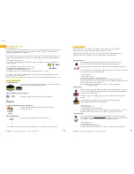
Err: 7
Possible error numbers and respective error cause:
7 Error while checking the basic value of the hall sensor
11 Error while loading the individual start screen
12 Error while saving the individual start screen
14 Not specified battery is connected
17 Battery voltages is too low for motor current offset-determination
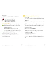
d) Further warning signs
In some cases, the SVE displays a warning signal that is not defined by a symbol. In this case, a skull symbol and
the text “Err: x” with the respective error number is displayed.
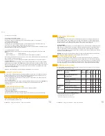
The symbol for battery charging is displayed on the screen as soon as the SVE is put into the charger.
It may take some time until the percentage battery capacity is displayed. Depending on the charging
level of the battery, the communication between the charging controller and the battery decreases.
As long as there has not been any communication between SVE and charging controller, the charging
bars of the charging indicator are shown in yellow.
When the battery is charged completely, 5 green charging bars are displayed and the battery capacity
is blinded out.
If a SVE has not been used for more than 2 weeks, the battery is turned into sleep mode automatically.
Warning!
- Always recharge the battery before complete discharge.
- The charger may only be used to charge the battery of the Smartblower blower.
- The battery may only be charged with an original charger of e-breathe.
- The charger is intended for indoor use only.
- The charger must not be covered during use.
- The charger has to be protected against moisture.
- Never short-circuit the battery.
- Never try to dismantle the battery.
- Never expose the battery to open fire; there is danger of explosion and/or fire.
3.6.3 Charging Indicator / Charging Progress
3.7.1 Functional Testing
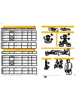
A functional test with a test tube of e-breathe can be performed before use. By doing so, you check, in
case of a warning, if the minimum airflow is still reached.
During Hood Operations:
Step 1:
Screw 2 particulate filters on the Y-Connector and mount the motor with the test tube on the Y-Connec-
tor. Afterwards, switch on the blower and wait ca. 45 seconds until is displayed. See if the ball is in the
right position above the line.
Step 2:
After that take the red test plug and click it on the particulate filter. You do all this during on-going ope-
rations. After a short time (ca. 30 seconds), the blower readjusts and provides a filter warning; the ball
should be above the line, in the area called “right”.
If no filter warning is provided, tape up the smallest holes one after the other in 30-second distances
until a filter warning is provided. The ball has to be above the line in the area called “right”.
- Check if the blower is assembled correctly and completely, clean and undamaged.
- The SVE has to be charged completely.
- Switch on the blower.
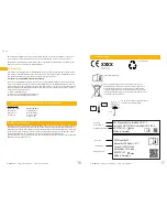
- Place the test tube at the blower
(see fig. 5)
.
- Wait ca. 45 seconds, then see if the minimum electricity capacity was reached.
Important!
-
The blower must not lie on any ground, but has to be hold in the hand so that it can aspirate
enough air.
-
Check the position of the ball in the tube. The ball must be in the field called “right” and float
a little bit above the mark
(see fig. 6)
.
If the minimum flow is not reached, check if
-
The flow meter is held upright.
-
The ball can move freely.
-
The filters are mounted correctly.
During Full-Face Mask Operation:
The test tube is attached to the blower with a particulate filter and switched on. When the blower eve-
ned out after ca. 45 seconds, it can be seen if the minimum airflow was reached.


