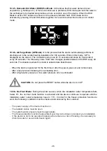
background image

22

14

A2

21

13

A1

6/

T3

4/

T2

2/

T1

5/

L3

3/

L2

1/

L1

-Q

22

14

A2

21

13

A1

6/

T3

4/

T2

2/

T1

5/

L3

3/

L2

1/

L1

-Q

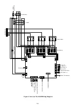
Figure

 4. Arceus 27 kW Wiring Diagram

Circulation 

Pump

3 Way Valve

Overheat Thermostat

CH 

Flow

 NTC

CH 

Return 

NTC

Boiler Tank 

NTC

DHW Solar STB

Water Pressure Sensor

DHW 

Outlet

 Sensor

Modbus Communication

Cascade Board

Wi-Fi


Board Connection

Mo
d

ulating Room Thermostat


Programmable Timer

Outdoor 

Temperature 

NTC

P

u

mp 
Encod

er

P

u

mp 
PWM

P

u

mp 
GND

Neutral

Terminal Block

Circuit Breaker

Contactor

Electric Heaters

Relay Boards

Neutral Bus Bar

Contactor

Electric Heaters

11

Summary of Contents for ARCEUS 12 CH

Page 1: ...ARCEUS ELECTRIC COMBI BOILER ARCEUS 6 9 12 15 18 24 27 kW MT CH ST USER AND INSTALLATION MANUAL...

Page 2: ......

Page 3: ...rams 8 5 4 Detailed View Component List and Installation 12 6 PACKAGING 15 7 ASSEMBLY 15 7 1 Selection of Device s Assembly Location 15 7 2 Wall Mounting of the Device 16 8 CONNECTIONS 17 8 1 Water Pi...

Page 4: ...se from material and workmanship provided that the instructions and warnings in the installation and operation manual are followed The commissioning operation must be carried out by the E C A authoriz...

Page 5: ...on and within the operating pressure range of installation so that freeze protection would be activated The freeze protection remains active even if the device is in OFF closed position 4 4 Commission...

Page 6: ...t breaker Anti freeze Protection for both Central Heating and Domestic Water Circuit Domestic Water Flow Control Pump Jamming Safety 3 Way Valve Jamming Safety Automatic Air Purge Expansion Tank 8 lit...

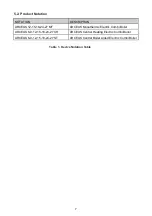
Page 7: ...US 12 15 18 24 27 MT ARCEUS Monothermic Electric Combi Boiler ARCEUS 6 9 12 15 18 24 27 CH ARCEUS Central Heating Electric Combi Boiler ARCEUS 6 9 12 15 18 24 27 ST ARCEUS Central Boiler Aided Electri...

Page 8: ...at CH Flow NTC CH Return NTC Boiler Tank NTC DHW Solar STB Water Pressure Sensor DHW Outlet Sensor Modbus Communication Cascade Board Wi Fi Board Connection Modulating Room Thermostat Programmable Tim...

Page 9: ...w NTC CH Return NTC Boiler Tank NTC DHW Solar STB Water Pressure Sensor DHW Outlet Sensor Modbus Communication Cascade Board Wi Fi Board Connection Modulating Room Thermostat Programmable Timer Outdoo...

Page 10: ...NTC CH Return NTC Boiler Tank NTC DHW Solar STB Water Pressure Sensor DHW Outlet Sensor Modbus Communication Cascade Board Wi Fi Board Connection Modulating Room Thermostat Programmable Timer Outdoor...

Page 11: ...at CH Flow NTC CH Return NTC Boiler Tank NTC DHW Solar STB Water Pressure Sensor DHW Outlet Sensor Modbus Communication Cascade Board Wi Fi Board Connection Modulating Room Thermostat Programmable Tim...

Page 12: ...ck 4 Neutral Terminal Block 5 Neutral Busbar 6 Cantactor 7 3 Way Valve 8 3 Bar Safety Valve 9 Electric Heaters 10 Main Heat Exchanger 11 Expansion Vessel 12 Drain Valve 13 Plate Heat Exchanger 14 Circ...

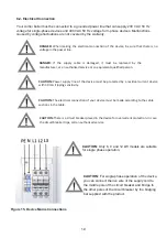
Page 13: ...Control Board Figure 6 Control Panel Elements Figure 6 1 Control Board Rear Cover and Terminal Connections 13...

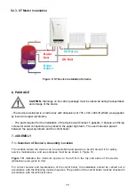
Page 14: ...4 1 MT Model Installation Figurel 7 Monothermic Device Installation Scheme 5 4 2 CH Model Installation Figure 8 CH Device Installation Scheme DHW Outlet DHW Inlet CH Flow CH Flow CH Return CH Return 1...

Page 15: ...dimensions of 735 x 345 x 490 HxWxD as supported by lower and upper styrofoams Boiler Exit CH Exit CH Return Boiler Return 7 1 Selection of Device s Assembly Location The location where the device can...

Page 16: ...as bathtubs shower cabinets and must be assembled at least 50 cm away from these areas Since the outer surface temperature of the device does not exceed 85 C at maximum heating power no special protec...

Page 17: ...3 4 outlet line hot b Domestic water pipe 1 2 outlet line hot c Domestic water pipe 1 2 inlet line cold d Central heating pipe 3 4 return line cold A suitable sized valve should be installed in the w...

Page 18: ...e hot b Boiler outlet line 1 2 hot c Boiler return line 1 2 cold d Installation Filling line 1 2 e Central heating pipe 3 4 return line cold a b c d e Figure 14 ST boiler water connections 8 1 2 HCH M...

Page 19: ...e device for overcurrent protection In case the circuit breaker trips call an authorized service 8 2 Electrical Connection Your combi boiler must be connected to a grounded power line that can supply...

Page 20: ...9 CH ST Single phase 3x10 39 B40 1P Three phase 5x2 5 13 B15 3P ARCEUS 12 MT CH ST Single phase 3x10 52 B63 1P Three phase 5x4 17 B20 3P ARCEUS 15 MT CH ST Three phase 5x6 22 B25 3P ARCEUS 18 MT CH S...

Page 21: ...hermostat T6360 7006907804 E C A Smart Combi Boiler Kit 7006907531 E C A Digital Room Thermostat Cordless Programmable CM727 7006902046 Poly 100 W Room Thermostat 7006903001 E C A Digital Room Thermos...

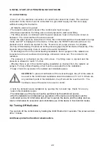
Page 22: ...er comes out This is done for all radiators The pressure is rechecked via the LCD screen The filling valve is opened and the pressure is allowed to reach 1 5 2 bar Whether there is air in the central...

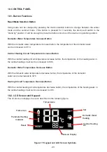
Page 23: ...ith the central heating circuit temperature increase button the temperature of the heating water in the central heating circuit can be increased to 80 C Domestic Water Temperature Decrease Button With...

Page 24: ...ssword value at parameter menu entry Reduces parameter value Indicates information value Indicates error history value Figure 18 Control Panel Button Configuration 10 2 1 Button Functions K5 K6 K1 K3...

Page 25: ...andby Mode Off Mode It is the mode in which the device can be set to standby mode In this mode central heating and domestic water heating demands cannot be met 10 3 2 Summer Mode In this mode the devi...

Page 26: ...is mode is activated are listed below When the device is powered for the first time or after the power goes out and comes back After a reset process following the overheating error After a high water...

Page 27: ...ture reaches to 15 C Below conditions must be provided and controlled by the customer for anti freze protection to work properly Power supply of the device must bu connected Radiator valves must be op...

Page 28: ...d by pressing the RESET button L43 Water Pressure Sensor Error This error is displayed if the pressure sensor is short or open circuit or damaged When this error is cleared normal operation begins L47...

Page 29: ...hibitor Sentinel X400 etc should be added to the installation water 12 3 Cleaning of Combi Boiler Keep the outer casing of the combi boiler clean by wiping it with a soft damp cloth Do not use strong...

Page 30: ...1 3x10 1 3x10 Power Cord CrossSec on mm 5x6 5x6 5x6 5x10 3 5x2 5 3 5x2 5 3 5x4 Protec on Class IPX4D IPX4D IPX4D IPX4D IPX4D IPX4D IPX4D Sound Level dB 42 42 38 38 38 38 38 Net Weight kg 26 26 27 27 2...

Page 31: ...odel identifier Space Heating Temperature application Medium Efficiency Class Water Heating Load Profile Rated heat output Prated ARCEUS Combi ERP Units CH ST Model Supplier s name or trademark E C A...

Page 32: ...8 U O U n n n n n n nmn n n 9 8 1 6 2 00 1 4 0 3 1 6 5 0 2 9 8 6 6 7 00 2 1 0 3 2 6 2 0 1 4 8aYU8Rna 8 nJ 8cLUFn U Fln E M U ln MUn n n 0 n Bnc8Wn 9cLUFnMan8 Yi n nga n n 81U U8 U BU U U U E U UP F 4...

Page 33: ...33...

Page 34: ...vl8 rvl X7 7 Lv Xh X EZ4T e i 4lz rlh7 l Y 4 h vR I4Y h5 lh4 Xh _ 7 Xh Xd7XhR VY J4Y h4 Y h4 7 0 Q H4 mv 4T T l Xh T 7Y X Xlh e h9 T 7Xe h Ylk hS kFc 4T v 4 vX X4 T lB W v T hS qvR J4X h4 lB T 4lf1 h...

Page 35: ...erial Number Submit Date and Location Maximum Repair Time 20 Work Days Warranty Time 3 Years AUTHORIZED SERVICE Title Address Tel Fax Assembly Date Date Signature and Seal FREE INITIAL START UP COUPON...

Page 36: ...PRODUCTION Organize Sanayi Bolgesi 3 Kisim Mustafa Kemal Boulevard No 13 45030 MANISA Tel 90 236 213 00 21 Fax 90 236 213 08 59 email emas emas com tr www emas com tr 7006910085 2 0...

Reviews: