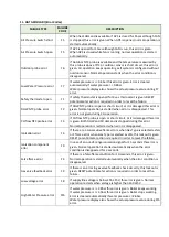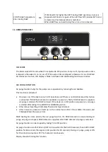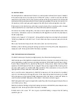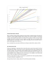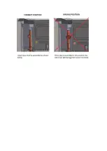
Setting the maximum outlet pressure;
The device is taken to maximum operation position.
Gas outlet pressure measurement port’s screw is loosened.
U manometer is connected to gas outlet pressure (ø9 mm) measurement port.
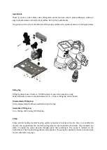
After removing the protection cap of maximum pressure regulator’s adjustment screw –shown by no 2
in Figure- , the gas flow towards the burner increases by slowly turning it clockwise, and otherwise it
decreases.
By monitoring the pressure values from U manometer, the required pressure value is obtained. Setting
of maximum outlet pressure is made only for natural gas, the adjust screw of maximum pressure
regulator is completely tightened.
Setting the minimum outlet pressure;
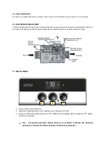
The device is taken to minimum operation by removing one of the gas modulation cables.
Gas outlet pressure measurement port’s screw is loosened.
Gas flow decreases by turning the minimum pressure regulator’s adjustment screw –shown by no 1 in
Figure- clockwise, and otherwise it increases.
The required pressure value is obtained by monitoring the pressure values from U manometer.
After making the setting, the screw removed from the outlet pressure measurement port is fastened
again and tightened for the measurement of gas valve’s outlet pressure.
The removed front panel and control panel are fastened again.
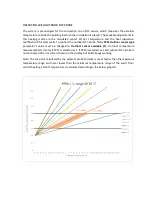
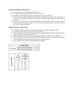
ECA GP 24 HM
Natural Gas
Max. Gas Pressure (mbar)
12,3
Min. Gas Pressure (mbar)
1,4
EC
A
G
P
2
4
HM
CH
Capacity
P07
Parameter
Value
11,3
51
13
60
16
70
20
82
24
99
Summary of Contents for GP11
Page 1: ...GP 11 13 16 20 24 kW HM HERMETIC MONOTERMIC COMBI BOILER SERVICE MANUAL...
Page 7: ...8 SERVICE PARAMETER LIST...
Page 8: ...9 OPERATION PARAMETERS...
Page 22: ......

