background image


1.


PRODUCT NOTATION 

GP 11/13/16/20/24 HM 

Definition 


E.C.A. GP 11/13/16/20/24 kW Hermetic Combi (monothermic 
model) 


2.


SAFETY SYSTEMS 

With the safety systems in your device, both you and your device are fully secured. These safety 
systems; 


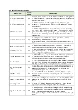
Flame Loss Protection


Boiler Over-heat Safety System (105°C)


DHW (Domestic Hot Water) Over-heat Safety System (71°C)


CH (Central Heating Water) Over-heat Safety System (95°C)


High Water Pressure Protection System (3 bar)


Low Water Pressure Protection System (0,8 bar)


Low Voltage Protection System (165 V AC)


Thermal Accumulation Protection System (with by-pass circuit and pump over-run)


Frost  Protection  System  (The  appliance  must  be  on  stand-by  to  activate  the  frost 
protection)


Water Flow Inspection. 


Pump Dry Run Protection System


3 Way Valve Anti-sticking Function


Automatic Air Vent


Expansion Vessel (6L)


3.


GENERAL FEATURES 


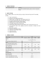
11 kW

13 kW

16 kW

20 kW

24 kW

Category

Type
Gas Inlet Pressure (Natural Gas G20)

mbar

Power

Unit

Pmin, heating power (thermal power)

kW

Pmax, heating power (thermal power)

kW

11,3

13

16

20

23,3

Qmin. Thermal Load

kW

Qmax. Thermal Load

kW

12,8

14,8

17,9

22,3

25,6

Gas Consumption

Unit

Natural Gas (at full power)

m

3

/h

1,38

1,58

1,93

2,41

2,76

Natural Gas (at min. power)

m

3

/h

NOx Class

Central Heating

Unit

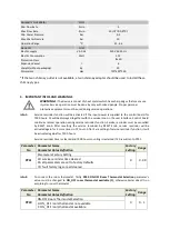
Min. Water Pressure

bar

Max. Water Pressure

bar

Operation Range (@Radiator heating)

°

C

Operation Range (@Underfloor heating)

°

C

30 - 50

0,8

3

30 - 80

8,2

9,2

0,96

3

20

Unit

GP

Product Type

I

2H

C

12(X)

, C

32(X)

,*C

42(X)

,*C

52(X)

Summary of Contents for GP11

Page 1: ...GP 11 13 16 20 24 kW HM HERMETIC MONOTERMIC COMBI BOILER SERVICE MANUAL...

Page 2: ...n System The appliance must be on stand by to activate the frost protection Water Flow Inspection Pump Dry Run Protection System 3 Way Valve Anti sticking Function Automatic Air Vent Expansion Vessel...

Page 3: ...ter 7500 hours Service reminder time is cleared and 7500 hours counting is restarted if 20 is written to PP31 Parameter No Parameter Name Parameter Value Definition Factory Setting Range PP31 Paramete...

Page 4: ...correctly connected and the function enabled Parameter No Parameter Name Parameter Value Definition Factory Setting Range PP15 Outdoor Sensor Type 0 0 1 0 Outdoor sensor not available 1 Outdoor sensor...

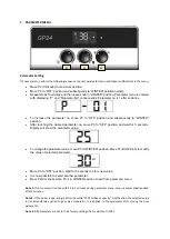
Page 5: ...that mode frost protection is ready to activate When device gave a fault turn knob to OFF position and wait 3 second for fixing the fault and then turn previous mode When this knob turns to left devi...

Page 6: ...t for 5 seconds Display will show the parameter value To change the parameter value move P3 to WINTER position Move P1 DHW knob to modify the value of selected parameter Move P3 to OFF position Wait f...

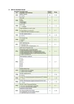
Page 7: ...8 SERVICE PARAMETER LIST...

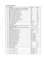
Page 8: ...9 OPERATION PARAMETERS...

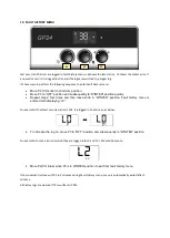
Page 9: ...four times and then leave knob in WINTER position Fault history menu is entered with displaying L0 For example if the latest occurred error is F01 it is logged in L0 and seen as below To increase the...

Page 10: ...not given during CH operation CH flow NTC probe error F3 If CH flow NTC probe is open or short circuit or it is damaged this error is given Both DHW and CH demand is stopped during this error Normal o...

Page 11: ...is not DHW demand this fuction is activated If DHW heat demand is available on power on firstly DHW demand is supplied air purge is started after DHW is closed If the device is in OFF position on powe...

Page 12: ...displayed on LCD Flame symbol is ON if the flame is available DHW INSTANTENOUS HEATING MODE The DHW Instantaneous function has higher priority than the central heating function DHW Instantaneous Heati...

Page 13: ...TC probe firstly PP15 Outdoor sensor type parameter s value must be changed to Outdoor sensor available 1 Outdoor temperature measurement starts only if PP15 is selected as 1 If PP15 is selected as 1...

Page 14: ...ting is restarted if 20 is written to PP31 ANTIFREEZE FUNCTION If the water temperature measured by the CH flow NTC probe is under the low limit for No frost ON temperature in table 1 the burner is tu...

Page 15: ...m and maximum heating capacity becomes adjusted by the determination of operation pressure range 15 SERVICE MODE Power off the control board Adjust the knob positions to P1 maximum P2 minimum P3 OFF P...

Page 16: ...r is completely tightened Setting the minimum outlet pressure The device is taken to minimum operation by removing one of the gas modulation cables Gas outlet pressure measurement port s screw is loos...

Page 17: ...as control The minimum and maximum operating pressures can be adjusted mechanically via the gas valve The modulation valve is set with the maximum output pressure the maximum pressure regulator adjust...

Page 18: ...ween 1 0 1 5 bars filling tap can be closed Disassemble of filling tap Firstly disassemble the flow manifold and turn the tap Assemble of filling tap Turn the tap until closing the filling tap Pump Pu...

Page 19: ...r is needed the 3 way motorized valve directs the central heating water from the main exchanger to the plate heat exchanger The plate heat exchanger allows heat to be transferred to the domestic hot w...

Page 20: ...erature increases or the sensor resistance increases as the temperature decreases NTC sensors are usually identified with nominal resistance values of 25 C However this value does not fully define the...

Page 21: ...t the start of operation the differential air pressure switch is on In the first stage the fan starts to run when the pressure difference rises above the set value within a certain period of time the...

Page 22: ......

Reviews: