A
B
DET
AIL
A
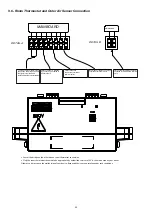
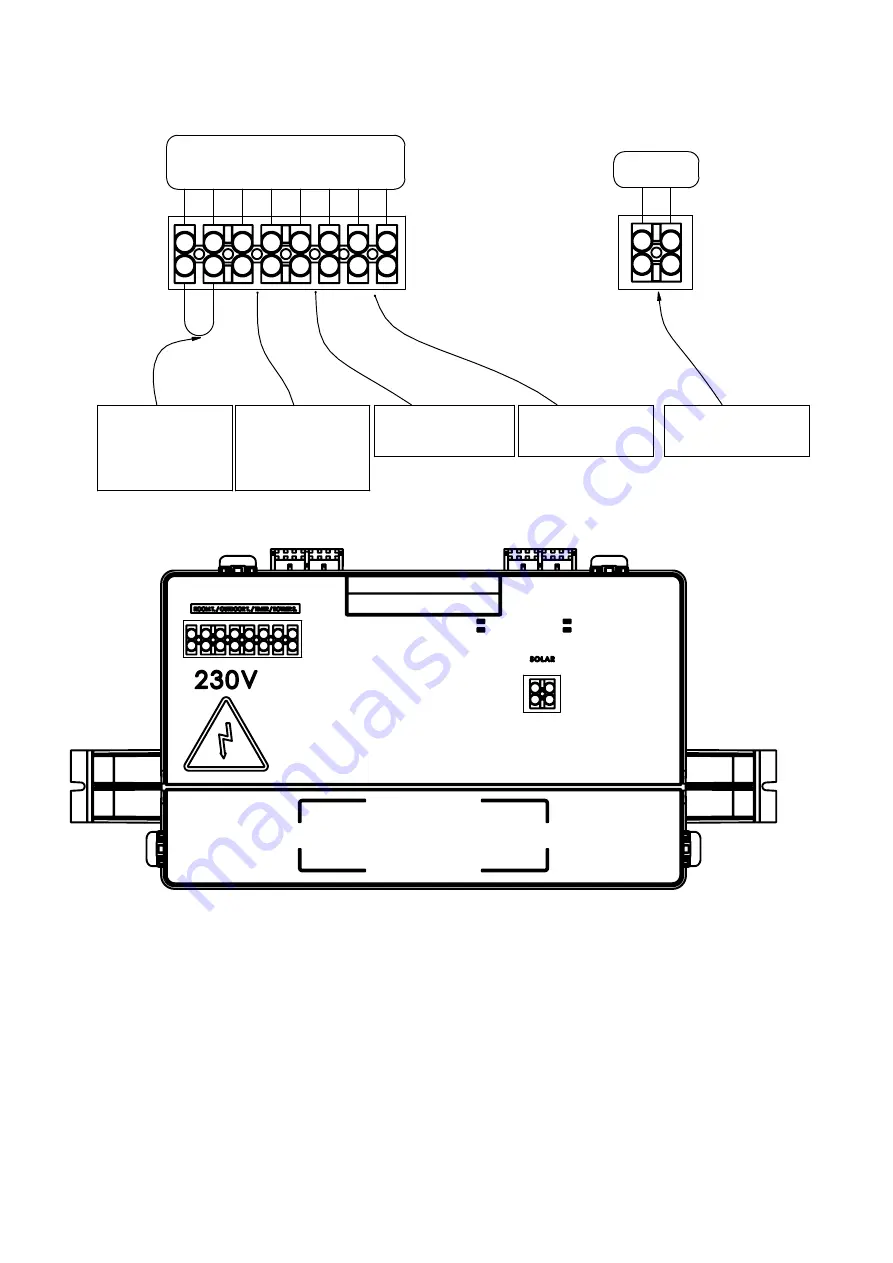
MAINBOARD
To make the room thermostat
connection, the bridge shown in
the figure is removed and
replaced with thermostat cables
Outdoor sensor is installed
by connecting its cables to
free terminals.
Timer cables are
connected to relevant
terminal points.
Boiler sensor cables connected
to relevant terminal points.
DETA
IL
B
MAINBOARD
Solar system connection cables are
connected to the indicated terminal
points.
9.6- Room Thermostat and Outer Air Sensor Connection
•
Cancel the bridge on the other side on room thermostat connection.
•
Only the room thermostats deemed to be appropriate by authorized services of E.C.A. should be used on your boiler.
Otherwise, it may cause the malfunction of your device. Responsibility is not undertaken under such conditions.
22
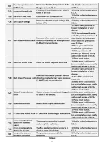
Summary of Contents for Proteus Premix PPR 14 HCH
Page 9: ...5 4 Technical Specifications 9 ...
Page 10: ...10 ...
Page 28: ...28 ...
Page 29: ...Table 4 29 ...
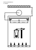
Page 32: ...16 INSTALLATION TEMPLATE 16 1 HM Model 32 ...
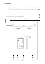
Page 33: ...E E L C 160 mm 00 160 mm cJiD E E o o L C E 16 2 HCH Model 33 ...
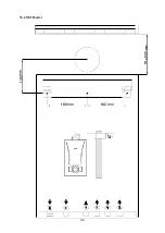
Page 34: ...E E L C 160 mm 00 C 160 mm E E o o L C E 16 2 HST Model 34 ...
Page 36: ...36 ...
Page 37: ...37 ...
Page 38: ...38 ...
Page 39: ...39 ...
Page 41: ...41 ...


