7
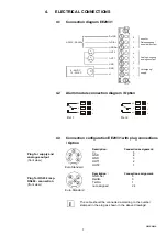
Versorgung /
supply
≅
8 - 48VDC
12 - 35VAC
GND
OUT 1
OUT 2
3
5
6
7
8
4
GND
2
V+
1
V
V
mA
mA
Analog Ausgang /
analogue output
RxD/B-
RS232 / RS485
serieller
Datenausgang /
serial data output
TxD/A+
GND Ser
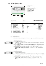
NC
3
NO
1
C
2
NC
6
NO
4
C
5
4.2
Alarm module connection diagram / Option
4.1
Connection diagram EE29/31
Rel 1
Rel 2
4.
ELECTRICAL CONNECTIONS
1
2
3
4
5
1
2
3
4
5
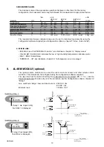
Description:
Connection assignment:
V+
5
GND
4
GND
3
OUT1
2
OUT2
1
Description :
Connection assignment:
GND-Ser
5
Rxd/B-
3
Txd/A+
1
not assigned
2.4
Euro Standard
Euro Standard
4.3
Connection configuration EE29/31 with plug connections
/ Option
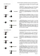
The cable should be connected according to the number
stamped in the plug as shown in the above drawings!
i
Hardware
Plug for supply and
analogue output
(front view)
Plug for RS232 resp.
RS484- connection
(front view)


