background image

Moisture in Oil Sensor

BA_EE381 // v05 / Modification rights reserved // 193021

User Manual

EE381

Summary of Contents for EE381

Page 1: ...Moisture in Oil Sensor BA_EE381 v05 Modification rights reserved 193021 User Manual EE381...

Page 2: ......

Page 3: ...ation 8 3 1 Installation Location 8 3 2 Installing the Probe directly into the Process 8 4 Electrical Connection 9 5 Operating Components 10 5 1 Circuit Board 10 5 2 Status LEDs 11 5 3 Display Module...

Page 4: ...his equipment does cause harmful interference to radio or television reception which can be determined by turning the equipment off and on the user is encouraged to try to correct the interference by...

Page 5: ...petition or forwarded to third parties Copies for personal use are permitted All information technical data and illustrations contained in these instructions are based on information available at the...

Page 6: ...nmental Aspects Products from E E Elektronik are developed considering all important environmental issues While disposing of the product environmental pollution should be avoided To dispose of the sen...

Page 7: ...istance to pollution of the E E HMC capacitive sensing elements series The sensor has two freely selectable and scaleable outputs for water activity temperature or water content in ppm The optional co...

Page 8: ...ectly into the process there should be a stop valve on both sides of the point of installation This makes it easy to remove the sensor for maintenance and calibration Step 1 Install the probe with the...

Page 9: ...User Manual EE381 Page 9 4 Electrical Connection Analogue output 1 7 6 5 2 3 4 1 V 2 GND 3 GND 4 OUT1 5 OUT2 6 NC 7 NC V mA V mA 10 30V DC 1 V 2 GND 10 30V DC...

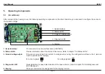
Page 10: ...e device Refer to chapter 5 2 Status LEDs 3 Current voltage output If the sensor is switched from current to voltage output using the configuration software the 2 jumpers must be positioned accordingl...

Page 11: ...Power LED flashing supply voltage applied Yellow Red The yellow and red LEDs are deactivated and currently have no function 5 3 Display Module Option Measurand Units SI US T Temperature C F aw Water...

Page 12: ...via LED on the circuit board Power LED green flashing Supply voltage applied Microprocessor is active LED D1 blue constantly lit sensing element damaged flashing sensing element bedewed condensation S...

Page 13: ...ply voltage Check wiring and supply voltage Green LED is illuminated continuously electronics defect contact the manufacturer Further self diagnosis i Error possible cause measures help 6 3 Replacemen...

Page 14: ...Temperature dependence aw 0 00022 0 0002 x aw x T C T T 20 C T 0 0003 C C Response time t90 in still oil at 20 C 68 F typ 10 min Temperature Oil temperature 40 120 C 40 248 F Accuracy Outputs Two free...

Page 15: ...Stainless steel Working temperature range Probe 40 120 C 40 248 F Electronics 40 80 C 40 176 F Display 20 50 C 4 122 F Storage temperature range 40 60 C 40 140 F Electromagnetic compatibility accordi...

Page 16: ...oulin 69130 Ecully Tel 33 4 74 72 35 82 E mail info epluse fr E E Elektronik Germany Sch ne Aussicht 8 C 61348 Bad Homburg Tel 49 6172 13881 0 E mail info epluse de E E Elektronik Italy Via Alghero 17...

Reviews: