background image

BA_EE741 // v1.7 // Modification rights reserved // 194408

User Manual

EE741

Inline Flow Sensor

for Compressed Air and Gases

Summary of Contents for EE741 Series

Page 1: ...BA_EE741 v1 7 Modification rights reserved 194408 User Manual EE741 Inline Flow Sensor for Compressed Air and Gases...

Page 2: ...equipment has been tested and found to comply with the limits for a Class A digital device pursuant to part 15 of the FCC Rules These limits are designed to provide reasonable protection against harmf...

Page 3: ...4 Inlet and Outlet Measurement Path 12 4 5 Installation of the Gauge Mounting Block 13 4 5 1 Gauge Mounting Block 13 4 5 2 Gauge Mounting Block with Flanges 13 4 5 3 Operating the Pipeline without Sen...

Page 4: ...uctions 1 2 1 Intended Use The inline flow sensor device is dedicated to the measurement of compressed air and non corrosive gases in pipelines Please consult the manufacturer before employing the dev...

Page 5: ...nd electrical connections shall be thoroughly checked by authorized staff before putting the system into operation Do not install or start start up a device supposed to be faulty Make sure that such d...

Page 6: ...ized flow and the temperature Depending on the ordered version the EE741 is available either as analogue version with analogue output current switch output and or pulse output for consumption metering...

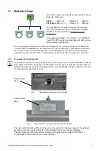
Page 7: ...cks The sealing plug included in the scope of supply enable the normal operation of the compressed air system when the sensing unit is removed 3 1 1 Changing the Pipe Diameter Upon delivery the factor...

Page 8: ...tput factory setting 4 20 mA or 0 20 mA is used for the actual flow or temperature measured values The analogue output is freely configurable and scalable via the display menu or the EE PCS Product Co...

Page 9: ...r pulse value m IMPL_MAX max pulse duration s NORMV_MAX max expected standard volume flow m h The totalized consumption is stored every minute and is retained even if the supply voltage is interrupted...

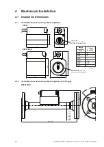
Page 10: ...1 DN321 1 1 4 DN40 1 1 2 DN50 2 1 only Rp thread Internal thread Whitworth thread according to EN 10226 old DIN 2999 or NPT Internal thread Whitworth thread according to EN 10226 old DIN 2999 or NPT...

Page 11: ...relevant for measurement accuracy as specified in the EE741 data sheet EE741 shall be located as far as possible from flow disturbances for instance at an appropriate distance before valves 4 2 1 Proc...

Page 12: ...ieces valves or sliders This can be accomplished by observing a minimum inlet and outlet path length which depends on both the nature of disturbance and the pipe diameter This applies to mounting the...

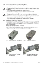
Page 13: ...A074540 HA074550 The seals shall not impact the cross section of the pipe or of the block All connections must be properly sealed and checked for tightness before use 4 5 3 Operating the Pipeline with...

Page 14: ...otective cap from the sensing head Fig 10 and insert carefully the sensing head of the sensing unit into the gauge mounting block Fig 10 Remove protective cap Make sure that the direction arrow on the...

Page 15: ...N 50178 SELV PEL 5 1 Connection Diagram Fig 12 M12 connector M12 4 pole connector according to IEC 61076 2 101 Analogue switch pulse output 1 V 2 Output 1 3 GND 4 Output 2 Modbus RTU 1 V 2 RS485 A D 3...

Page 16: ...value Data record 4 Consumption meter status 05 DIF 32 bit real 16 VIF volumes in m XX XX XX XX Cur consumption value Data record 5 Flow velocity 05 DIF 32 bit real 7F VIF manufacturer specific in m...

Page 17: ...w Nm h 32 bit float 31019 3FA MIN value standard volume flow Nm min 32 bit float 31021 3FC MIN value standard volume flow l min 32 bit float 31023 3FE MIN value standard volume flow l s 32 bit float 3...

Page 18: ...requires less Please note For obtaining the correct floating point values both registers have to be read within the same reading cycle The measured value can change between two Modbus requests therefo...

Page 19: ...V n m3 h 1 Temperature T C Tab 1 Scheme of process data input Per factory default the measurands data type is FLOAT32 more exactly 32 bit single precision float The parameters may freely be selected v...

Page 20: ...When an adjustment is performed using the EE PCS a suitable air velocity temperature reference has to be used 6 Display The LCD display optional shows the actual measured values and the overall consu...

Page 21: ...dard flow Fig 19 Status display Fig 20 Measured value display Explanation of the symbols Output 1 set to analogue output Output 2 set to pulse output consumption Output 1 set to switching output statu...

Page 22: ...ulse output measurand switch setup Pipe diameter Set the pipe diameter see 2 1 1 on page 7 Display Set the measuring mode and the display orientation Process parameter Set the operating pressure and t...

Page 23: ...uts operate normally Remedy Return the device to the manufacturer for service 2 Display error green LED flashes red LED lights up Cause The display or the communication with the display is faulty Cons...

Page 24: ...or element within the sensing head Allow the sensing head to dry free 9 Ordering Guide for Accessories Designation Order number Inlet and outlet path BSP thread stainless steel for gauge mounting bloc...

Page 25: ...6 W Operating pressure max 16 bar 232 psi PN16 Ambient temperature range with display 0 50 C 32 122 F without display 20 60 C 4 140 F Medium and storage temperature range 20 60 C 4 140 F Humidity work...

Page 26: ...0 2500 250 Standard volume flow l s DN15 0 20 14 1 4 DN20 0 35 25 2 5 DN25 0 55 40 4 Standard volume flow SCFM DN15 0 44 30 3 0 15 0 07 DN20 0 76 53 5 3 0 25 0 12 DN25 0 117 88 8 8 0 35 0 17 Mass flow...

Page 27: ...0 8300 5800 580 DN50 0 13300 10000 1000 Standard volume flow l s DN32 0 83 56 5 6 DN40 0 139 97 9 7 DN50 0 222 167 16 7 Standard volume flow SCFM DN32 0 176 117 11 7 0 55 0 25 DN40 0 294 200 20 0 9 0...

Page 28: ...s steel AISI 316L FKM Glas polyimide coating Aluminium eloxiert aluminum anodized Edelstahl 1 4404 stainless steel AISI 316L Messumformer sensing unit Geh use housing Dichtung sealing Stecker connecto...

Page 29: ...oulin 69130 Ecully Tel 33 4 74 72 35 82 E mail info epluse fr E E Elektronik Germany Sch ne Aussicht 8 C 61348 Bad Homburg Tel 49 6172 13881 0 E mail info epluse de E E Elektronik Italy Via Alghero 17...

Reviews: