12
5.2
1 point humidity calibration
When the working range is limited to a certain more narrow range, a calibration at one
humidity point is absolutely sufficient.
This calibration causes an extra inaccuracy for the rest of the working range.
Procedure for 1 point humidity calibration:
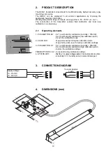
1.
Insert the sensor probe into the reference chamber 1 (humidity calibration point) and
stabilise for minimum 30 min.
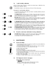
2. PUSHBUTTON S1
(calibration point > 50%RH.): Pressing the button for 3 seconds
starts the procedure for the low calibration point. The calibration mode is indicated by
the lit LED "Calib" and by the symbol "CAL" on the LC display.
or
PUSHBUTTON S2
(calibration point < 50%RH): Pressing the button for 3 seconds
starts the procedure for the low calibration point. The calibration mode is indicated by
the lit LED "Calib" and by the symbol "CAL" on the LC display.
3. PUSHBUTTON S1 (up)
und
S2 (down)
: Pressing the two buttons will adjust the
measuring value in steps of 0.1% up or down to the reference value. The actual mea-
suring value is indicated on the display or can be measured with the analogue output.
4. PUSHBUTTON S1
: Pressing the button for 3 seconds the calibration value and the
procedure is ended. Exiting the calibration mode is indicated by deactivation of the
LED "Calib" and the symbol "CAL" on the LC display.
or PUSHBUTTON S2
: Pressing the button for 3 seconds the calibration procedure will
be ended without storing the calibration values. Exiting the calibration mode is indica-
ted by deactivation of the LED "Calib" and the symbol "CAL" on the LC display.
5.3
Reset the customised calibration to factory calibration:
PUSHBUTTON S1 and S2
: In neutral mode pressing both buttons simultaneously for
5 seconds customer calibration settings are reset to factory calibration.
A short flash of the LED "Calib" indicates the reset.
6.
MAINTENANCE
6.1
Sensor exchange
•
After changing the sensor it is necessary to perform a two point calibration to
reach the specified accuracy again!
•
The factory calibration is no longer valid after performing a sensor exchange!
•
Touch the sensor elements on the connection wires only!
1.
Switch off the supply voltage
2.
Unscrew the filter cap
3.
Pull out the humidity sensor element with a tweezer
4.
Put in the new humidity sensor - the active side (side with the sensor pads) has
to face the inside. (see diagram)
5.
Screw the filter cap on again (in case of pollution replace it by a new filter cap)
6.
Switch on the supply voltage
7.
Perform a humidity calibration (refer to 2 point humidity calibration)
6.2
Self diagnosis and error messages
Status LED on the circuit board:
•
Green LED
flashing
⇒
Supply voltage applied / Microprocessor is active
constantly lit
⇒
Humidity sensor element damaged
S1
S2
S1
S2
Calib
S1
Calib
S2
S1
S2
aktive Seite /
active Side
Summary of Contents for EE99-1 Series
Page 19: ......


