User Manual HTS801
Humidity and Temperature Sensor for High Humidity and Chemically Polluted Conditions | 20
3.5.6.
RS485 Module - Modbus RTU (Option J3)
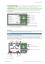
Up to 32 HTS801 sensors with Modbus RTU interface can be connected in an RS485 bus system (1 unit load).
Slave n
(max. 32)
Slave 2
Slave 1
Slave 3
Modbus RTU Master
Fig. 22 2-wire RS485 bus
PLEASE NOTE
Both ends of the bus shall be terminated with a resistor R
a
=.120.Ω.
The setup of the Modbus RTU communication can be performed via PCS10 Product Configuration Software or via
display and push-buttons, see chapter 11.3, Fig. 56 Modbus settings.
Modbus RTU protocol settings
Factory settings
User selectable values (via PCS10)
Baud rate
9 600
9 600,.19 200,.38 400,.57 600,.76 800
Data bits
8
8
Parity
Even
None, odd, even
Stop bits
1
1, 2
Modbus address
230 (0xE6)
1...247
Tab. 2
Modbus RTU protocol settings
PLEASE NOTE
The.recommended.settings.for.multiple.devices.in.a.Modbus.RTU.network.are.9 600,.8,.even,.1.
3.5.7.
Ethernet Module - Modbus TCP (Option J4)
The Ethernet module features power over Ethernet (PoE) and RJ45 connector with IP65 protection rating.
PLEASE NOTE
The Ethernet connection shall be disconnected before opening the enclosure.
Available TCP and UDP Ports
▪.
Modbus TCP: Port 502
See.“Modbus.TCP/IP.implementation.guide”.which.can.be.found.at
www.modbus.org/docs/Modbus_Messaging_Implementation_Guide_V1_0b.pdf
.
The unit identifier of the MBAP header is not used and can be any value from 0 to 255.


