PROGRAMMING
4-4
November 1998
Part No. 001-7600-001
in the Screen menu (see Section 4.4.3), Memory
Channel screen (see Table 4-1), and DTMF Autodial
screen (see Table 4-3).
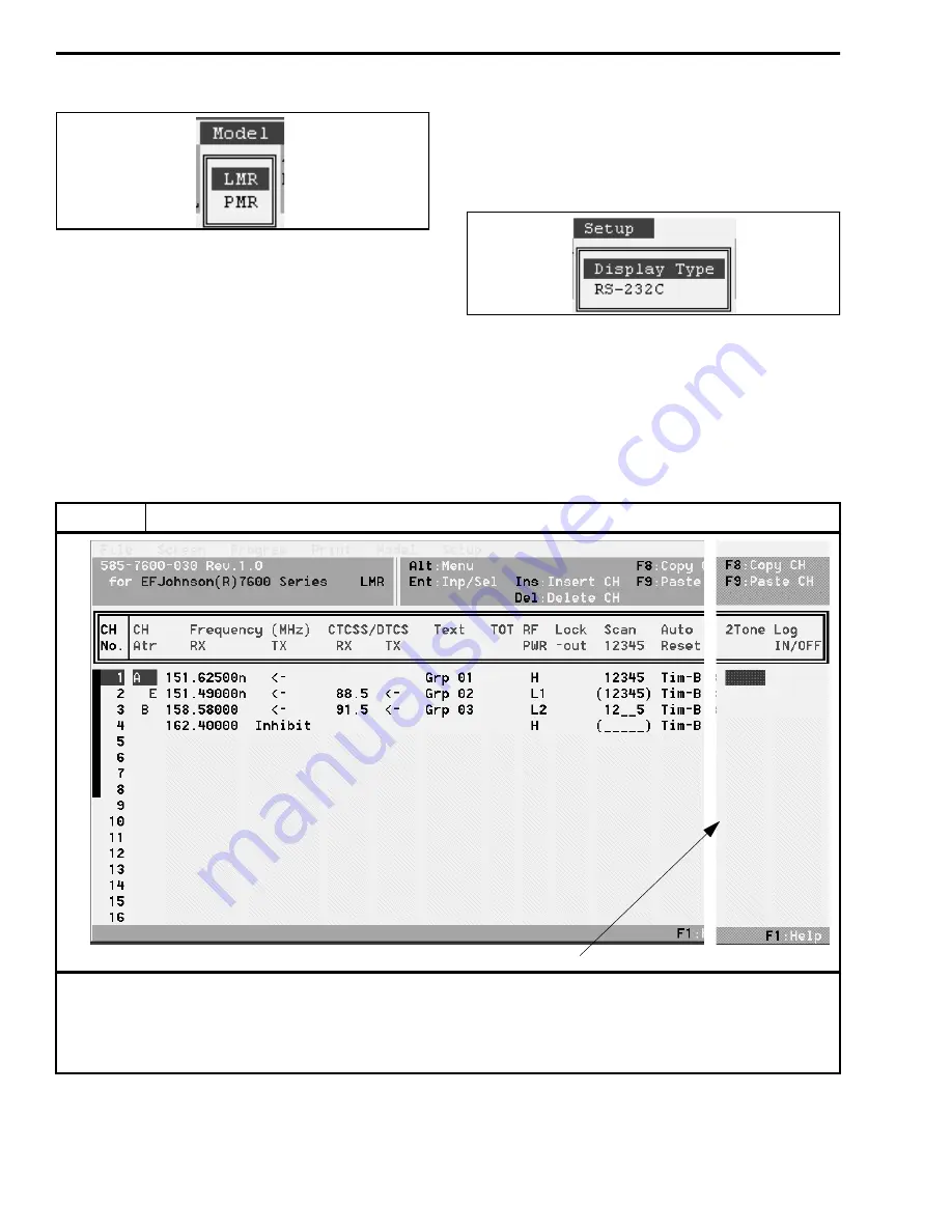
PMR - Selects PMR (European) models. Selecting
this model displays unique parameters for program-
ming a 5-tone option. As with the LMR selection,
unique parameters are displayed in the Screen menu
and Memory Channel and DTMF Autodial screens.
Refer to Section 4.5 for more information on PMR
models.
4.4.7 SETUP MENU
Display Type - Select the color or monochrome 1 or 2
display modes.
RS-232C - Selects the computer serial port being used
to connect the computer to the transceiver.
Table 4-1 Memory Channel Screen Description (LMR Models)
Parameter
Description
Bank Select
Up to 32 channels or two banks of 16 channels can be programmed. To program the channels as two banks, first
program the “MR-CH Bank/Free” parameter in the Key and Display Assign screen for “Bank” as described in Table 4-2. In
addition, a “Bank” option switch must be programmed in this screen to select banks. To switch between banks when
programming channels, press the PgUp/PgDn keys.
NOTE: To display this part of the screen, scroll over using the
→
arrow key
.
Summary of Contents for 761X
Page 9: ...GENERAL INFORMATION 1 4 November 1998 Part No 001 7600 001 This page intentionally left blank ...
Page 11: ...GENERAL INFORMATION 1 6 November 1998 Part No 001 7600 001 NOTES ...
Page 43: ...PROGRAMMING 4 18 November 1998 Part No 001 7600 001 This page intentionally left blank ...
Page 87: ...UHF 7640 EXPLODED VIEW 7 22 November 1998 Part No 001 7600 001 FOLDOUT VHF Exploded View ...
Page 90: ...8 3 November 1998 Part No 001 7600 001 VHF 7610 MAIN BOARD BOTTOM VIEW FOLDOUT ...
Page 91: ...8 4 November 1998 Part No 001 7600 001 VHF 7610 MAIN BOARD TOP VIEW ...
Page 94: ...8 7 November 1998 Part No 001 7600 001 UHF 7640 MAIN BOARD BOTTOM VIEW FOLDOUT ...


