PROGRAMMING
4-10
November 1998
Part No. 001-7600-001
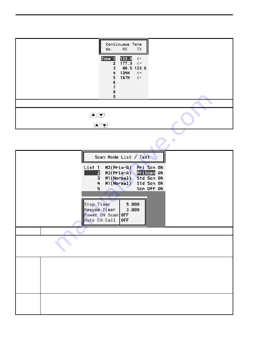
Table 4-4 Continuous Tone Screen Description
Description
The continuous tones programmed in this screen are selected by pressing the C.Tone CH Ent function key (see
Table 4-2) and then pressing the up/down
keys. This allows the user to select the continuous tone being transmitted
and received on the current channel. To transmit or receive using the codes programmed for the channel in the channel screen
(see Table 4-1), select “TON--M” using the
keys.
Table 4-5 Scan Function Screen Description
Parameter
Description
This screen is used to configure each of the up to five scan lists that can be selected. Channels are assigned to a scan list
in the Memory Channel screen described in Table 4-1 and by the TAG key described in Table 4-2. Scanning is turned on and
off and a specific scan mode is selected by the SCAN key also described in Table 4-2. Scanning may be enabled at power on
(see following) and by placing the microphone on-hook (see “Hanger Action” in Table 4-2).
Scan Mode The following conditions are programmable:
Scan Off - Deactivates that scan list so that it cannot be selected.
M1 (Normal) - Selects normal (non-priority) scanning from the lowest to highest channel.
M2 (Prio A) - Selects scanning from the lowest to highest channel while checking the Priority A channel. If
scanning is turned off while receiving a message in the scan mode, the transceiver switches to that channel.
M 3 (Prio A) - Same as Mode 2 except that if scanning is turned off while receiving a message, the Priority A
channel is selected.
Text
Programs the text that is displayed while scanning with that scan list selected. If “OFF” is programmed, the text
is not displayed. Instead, the alpha tag (or channel number) programmed for each channel is displayed as the
channel is scanned. The characters and other information described for “TEXT” in Table 4-1 also applies to this
text.
Summary of Contents for 761X
Page 9: ...GENERAL INFORMATION 1 4 November 1998 Part No 001 7600 001 This page intentionally left blank ...
Page 11: ...GENERAL INFORMATION 1 6 November 1998 Part No 001 7600 001 NOTES ...
Page 43: ...PROGRAMMING 4 18 November 1998 Part No 001 7600 001 This page intentionally left blank ...
Page 87: ...UHF 7640 EXPLODED VIEW 7 22 November 1998 Part No 001 7600 001 FOLDOUT VHF Exploded View ...
Page 90: ...8 3 November 1998 Part No 001 7600 001 VHF 7610 MAIN BOARD BOTTOM VIEW FOLDOUT ...
Page 91: ...8 4 November 1998 Part No 001 7600 001 VHF 7610 MAIN BOARD TOP VIEW ...
Page 94: ...8 7 November 1998 Part No 001 7600 001 UHF 7640 MAIN BOARD BOTTOM VIEW FOLDOUT ...


