OPERATION
2-4
September 2001
Part No. 001-5100-001
Channel Switch -
This 16-position switch allows up
to 16 channels to be selected. This switch operates in
conjunction with up to 16 programmable zones to
allow up to 256 channels to be selected.
Antenna Connector -
Connection point for the
antenna. Make sure that the antenna is tight before
using the radio.
Emergency Switch -
If the radio is programmed for
emergency transmissions, pressing this switch alerts a
dispatcher, for example, of an emergency condition.
Refer to descriptions in Sections 2.6.11 and 2.7.10 for
more information.
2.3.3 SIDE CONTROLS
Option Switches 1, 2, and 3 -
These switches can be
system operator programmed to control a specific
function (see Section 2.2).
PTT Switch -
This switch is pressed to turn the trans-
mitter on. The indicator on the top panel lights red
when the transmitter is keyed.
Battery -
To remove the battery, press the release on
the bottom toward the front of the transceiver and slide
the battery outward.
Accessory Connector -
Connection point for optional
accessories such as a speaker/microphone.
2.3.4 DISPLAY
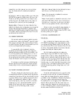
The front panel display is shown above. In the
conventional mode, if the Display Information option
switch is programed, either the channel number,
channel name, or frequency can be selected (see
Section 2.6.2).
The following information is indicated in the
display:
Alphanumeric Characters -
These eight characters
indicate the selected channel, error conditions, and
other information.
Sec -
Indicates that transmissions are encrypted (see
Section 2.4.13).
Dig -
Indicates that a digital (Project 25) conventional
channel is selected.
Rx -
Indicates that a carrier is being detected on the
selected or scanned channel. This indication is
displayed in conjunction with a green LED on the top
panel (see Section 2.3.2).
Tx -
Indicates the transmitter is keyed. This indication
is displayed in conjunction with a red LED on the top
panel.
Pgm -
Indicates that the keypad programming mode is
selected (see Section 2.9).
SL -
Indicates that the displayed channel is in the scan
list (see Section 2.5.7).
Pri -
Indicates that the displayed channel is
programmed as the current group’s priority channel
(see Section 2.6.13).
Option Switches
PTT Switch
Battery Pack
Accessory
Connector
Sec
Dig
Rx
Tx
Pgm
SL Pri
Call ID
Scan
Alphanumeric Display


