1-1
April 1999
Part No. 001-9800-600
GENERAL INFORMATION
1.1 SCOPE OF MANUAL
This addendum updates current LTR® 9800-
series service manuals with information needed to
service 9800-series LTR-Net™ transceivers. The LTR
service manuals it updates are as follows:
984x Series UHF - Part No. 001-9840-202
988x/989x 800/900 MHz - Part No. 001-9880-200
98xx Series UHF/800/900 MHz - Part No.
001-9800-200 (when available)
1.2 DIFFERENCES BETWEEN LTR AND
LTR-NET VERSIONS
The difference between LTR and LTR-Net
versions of the 9800-series transceivers is the operat-
ing software. All electrical and mechanical compo-
nents remain the same. Therefore, use this addendum
for Operation and Programming information for LTR-
Net models, and use the current sections of your
service manual for Installation, Circuit Description,
Parts List, Schematic Diagram, and PC Board Layout
information.
Different software is used to program LTR and
LTR-Net versions of this transceiver. The LTR-Net
software is a Windows 95/NT program, and the LTR
software is a DOS program. Therefore, either
Windows 95 or NT 4 or later is required to program an
LTR-Net transceiver. The part numbers of this soft-
ware are shown in Table 1-1.
1.3 TRANSCEIVER IDENTIFICATION
The transceiver identification number is printed
on a label that is attached to the chassis. In addition, it
is programmed into memory and can be read using the
programmer. The information contained in this
number is as follows
.
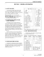
1.4 PART NUMBER BREAKDOWN
The following is a breakdown of the part number
used to identify this transceiver.
242 - 9 8 x x - x x x x
Band
Config.
Freq Range
Signaling
Type
1 = Low tier, dual BW
2 = Mid tier, dual BW*
3 = High tier, dual BW
4 = Low tier, 12.5 kHz
5 = Mid tier, 12.5 kHz*
6 = High tier, 12.5 kHz
8 = High tier rem, dual BW
0 = High tier rem, 12.5 kHz
1 = VHF*
4 = UHF
8 = 800 MHz
9 = 900 MHz
2 = LTR
4 = Multi-Net
6 = LTR-Net
8 = Data only LTR
9= Data only M-Net
0 = Conv only*
0 = Full band (800/
900 MHz)
3 = 430-470 MHz
5 = 470-512 MHz
1 = Low Pwr std*
2 = Mid Pwr std
3 = High Pwr std
6 = L.P. no acc*
7 = M.P. no acc
8 = H.P. no acc
* These configurations are currently not available
C = Compander
D = Data/Acc
Cable
E = Encryption/
Compander
H = Horn/Acc
Cable
Options
98xx
x
A
10 9
A
12345
Model
Revision
Letter
Manufacture
Date
Warranty
Number
Week No. of Year
Last Digit of Year
A = Waseca
Type
Plant
From P.N.
1 = Mid pwr LTR
2 = High pwr LTR
3 = High pwr Conv
4 = Mid pwr LTR-Net
5 = High pwr LTR-Net
6 = Mid pwr Multi-Net
7 = High pwr Multi-Net
8 = Mid pwr Data
9 = High pwr Data
0 = Mid pwr Conv
NOTE: Mid power = 25W
UHF, 15W 800/900 MHz;
High power = 40W UHF,
30W 800/900 MHz)
SECTION 1 GENERAL INFORMATION


