background image

2

E-flite Fokker DVII 250 Slow Flyer Assembly Manual

Using the Manual

This manual is divided into sections to help make 

assembly easier to understand, and to provide breaks 

between each major section. In addition, check boxes 

have been placed next to each step to keep track 

of its completion. Steps with a single circle (

) are 

performed once, while steps with two circles (


indicate that the step will require repeating, such as for 

a right or left wing panel, two servos, etc.

Remember to take your time and follow the directions.

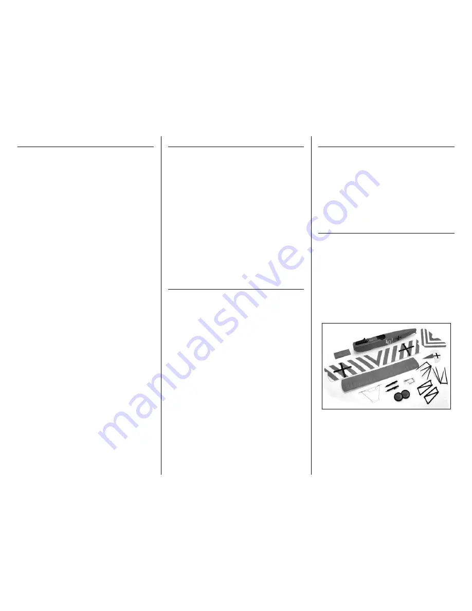
Contents of Kit/Parts Layout

Replacement Parts

EFL1976 

Wing Set

EFL1977 

Fuselage

EFL1978 

Tail Set

EFL1979 

Cowling

EFL1980 

Wheel Set

EFL1981 

Landing Gear

EFL1982 

Lower Gear Spreader

EFL1983 

Wing Struts

EFL1984 

Machine Gun Set

EFL1985 

Hardware pack

Introduction

Loved by the pilots who flew it and feared by those 

who flew against it, the Fokker DVII is regarded by 

many as the greatest fighter of WWI. E-flite brings this 

Great War legend to life with this remarkable foamy 

slow flyer that comes out of the box loaded with scale 

details. Details like molded machine guns, accurately 

modeled interplane struts, a dummy Mercedes engine 

and an intricately detailed cooling grille, just to name 

a few. Even the vibrant trim scheme that comes pre-

printed on the foam is an authentic reproduction of 

the markings on the DVII flown by German ace, Ernst 

Udet.

When matched with E-flite’s Park 250 brushless 

outrunner motor, the Fokker DVII 250’s featherlight 

wing loading and stunning scale appearance make for 

a majestic slow flyer experience unlike any other.

Important Information  

Regarding Warranty Information

Please read our Warranty and Liability Limitations 

section on Page 24 before building this product. If you 

as the Purchaser or user are not prepared to accept the 

liability associated with the use of this Product, you are 

advised to return this Product immediately in new and 

unused condition to the place of purchase.

Table of Contents

Specifications ......................................................... 1

Introduction ........................................................... 2

Important Information Regarding  

Warranty Information ........................................ 2

Using the Manual ................................................... 2

Contents of Kit/Parts Layout .................................... 2

Recommended Radio Equipment ............................. 3

Required Tools and Adhesives ................................. 3

Brushless Outrunner Setup ...................................... 3

Optional Accessories .............................................. 3

Note on Lithium Polymer Batteries ........................... 3

Warning ................................................................ 3

Motor Installation - Carbon Tube ............................. 4

Motor Installation - Firewall Mount .......................... 5

Speed Control Installation ....................................... 6

Servo Installation .................................................... 7

Stabilizer and Rudder Installation ............................ 9

Connecting the Linkages ....................................... 11

Cowling Installation .............................................. 13

Scale Accessory Installation .................................. 14

Bottom Wing ....................................................... 14

Cabane Strut Installation ....................................... 14

Top Wing and Outer Strut Installation .................... 15

Landing Gear Installation ...................................... 16

Rigging Installation ............................................... 18

Center of Gravity ................................................. 22

Control Throws..................................................... 22

Preflight ............................................................... 23

Flying Your Fokker DVII Slow Flyer ........................ 23

Range Test Your Radio .......................................... 23

Safety Do’s and Don’ts for Pilots ............................ 24

Daily Flight Checks ............................................... 24

Warranty Information ........................................... 24

Compliance Information for the European Union .... 26

2009 Official Academy of  

Model Aeronautics Safety Code ....................... 26

Summary of Contents for Fokker DVII 250 Slow Flyer ARF

Page 1: ...tions Wingspan 34 0 in 865mm Wing Area 310 sq in 19 4 sq dm Length 26 5 in 672mm Weight w o Battery 7 20 7 50 oz 204 212 g Weight w Battery 8 50 9 00 oz 240 255 g Fokker DVII 250 Slow Flyer ARF Assemb...

Page 2: ...en matched with E flite s Park 250 brushless outrunner motor the Fokker DVII 250 s featherlight wing loading and stunning scale appearance make for a majestic slow flyer experience unlike any other Im...

Page 3: ...Direct Drive Prop EFLA1010 10 Amp Pro Brushless ESC EFLB0990 7 4V 800mAh 2 Cell Li Po JST Balance Optional Accessories EFLA110 Power Meter EFLC3005 Celectra 1 to 3 Cell Li Po Charger EFLC505 Intellig...

Page 4: ...ng them to their proper locations is not an issue 2 Locate the 6mm x 42mm carbon tube Follow the instructions included with the motor to glue using RTV silicone the motor to the motor tube Be careful...

Page 5: ...ods from the tubes in the fuselage at this time to keep them from sliding out and getting bent Both pushrods are the same length so returning them to their proper locations is not an issue 2 The motor...

Page 6: ...rewall as shown Speed Control Installation Required Parts Fuselage assembly Speed control Tie wrap not included Two sided tape 1 Mount the speed control using two sided tape to the front of the fusela...

Page 7: ...the servo as far back in the opening as possible Use a pencil to mark the position for the screws that will be used to secure the rudder servo 3 Use a pin drill and 1 16 inch 1 5mm drill bit to drill...

Page 8: ...at Steps 2 through 5 to install the elevator servo Note the direction of the output of the elevator servo 7 Use a pin drill and 1 16 inch 1 5mm drill bit to enlarge the outermost hole in the servo arm...

Page 9: ...ing gear is installed Stabilizer and Rudder Installation Required Parts Fuselage Stabilizer elevator Fin rudder Micro control horn 2 Micro control horn backplate 2 Required Tools and Adhesives Foam sa...

Page 10: ...ops of foam safe CA to the joint between the backplate and control horn to keep it secure for the life of your model 5 Repeat Steps 1 through 4 to install the control horn on the rudder Note the direc...

Page 11: ...hat the stabilizer is square to the fuselage by measuring from a center point on the fuselage to each stabilizer tip Use a hobby knife to enlarge the slots in the fuselage if any adjustments are requi...

Page 12: ...d fin in the neutral position 6 Turn on the transmitter and make sure the rudder stick and trim are centered Use a 1 Phillips screwdriver to tighten the 1 5mm machine screw that will secure the pushro...

Page 13: ...the propeller installed The plane could move and cause serious injury Always check the motor without the propeller to avoid injury 1 Slide the cowling on the fuselage Use the three screws removed fro...

Page 14: ...Bottom wing 2mm x 8mm wood screw 4 Required Tools and Adhesives Phillips screwdriver 1 1 Use a 1 Phillips screwdriver and four 2mm x 8mm wood screws to secure the bottom wing to the fuselage Ensure y...

Page 15: ...bane strut has been practiced mix a small amount of 30 minute epoxy and apply it to the ends of the strut Insert the strut in the fuselage as described previously Install both struts at this time Top...

Page 16: ...uired Tools and Adhesives Hobby knife with 11 blade Foam safe CA Low temp hot glue 1 Slide one of the wheels onto the landing gear The wheel should rotate freely on the gear If not use a hobby knife a...

Page 17: ...the cowling Press the gear in until fully seated making sure not to damage the fuselage in the process 6 You may find the gear is slightly loose when installed Use foam safe CA to glue the landing ge...

Page 18: ...rigging through a needle to make it easier to pass the rigging through the holes especially the tubes in the fuselage near the bottom wing Another option is to soak the last 4 inches 100mm of the rig...

Page 19: ...complete the first stage of rigging tie the rigging at the top of the strut as shown Use low tack tape to secure the tape on the underside of the bottom wing The end taped will be secured once the ri...

Page 20: ...down and through the forward tube in the fuselage This line will be in front of all the other rigging lines 14 After exiting the fuselage route the rigging up to the forward hole in the outer strut Ma...

Page 21: ...oint the rigging passes through the struts Allow the CA to fully cure before moving your model Don t forget to tie the ends that were taped to the bottom of the wing at this time as well 18 Use a smal...

Page 22: ...n the transmitter and receiver of your Fokker DVII 250 Slow Flyer Check the movement of the rudder using the transmitter When the stick is moved right the rudder should also move right Reverse the dir...

Page 23: ...that will help to establish a longer glide path and to make landings easier Before taxiing out to the runway double check all controls are working in the correct direction and functioning properly You...

Page 24: ...rections Warranty Information Warranty Period Exclusive Warranty Horizon Hobby Inc Horizon warranties that the Products purchased the Product will be free from defects in materials and workmanship at...

Page 25: ...ditional protection Ship via a carrier that provides tracking and insurance for lost or damaged parcels as Horizon is not responsible for merchandise until it arrives and is accepted at our facility A...

Page 26: ...hold waste disposal service or where you purchased the product Age Recommendation 14 years or over Not a toy Not intended for use by children without direct adult supervision 2009 Official Academy of...

Page 27: ...ndividuals properly licensed by the FCC are authorized to operate equipment on Amateur Band frequencies 6 I will not knowingly operate my model aircraft within three 3 miles of any preexisting flying...

Page 28: ...61822 USA 877 504 0233 Horizon Hobby UK Units 1 4 Ployters Rd Staple Tye Harlow Essex CM18 7NS United Kingdom 44 0 1279 641 097 Horizon Hobby Deutschland GmbH Hamburger Strasse 10 25335 Elmshorn Germ...

Reviews: