background image

7

E-flite Fokker DVII 250 Slow Flyer Assembly Manual

Servo Installation

Required Parts

Fuselage 

Servo with hardware (2)

Receiver
Micro pushrod connector (2)
Micro pushrod connector backplate (2)

Required Tools and Adhesives

Pin drill 

Thin CA

Pliers 

Pencil

Phillips screwdriver: #0, #1

Drill bit: 1/16-inch (1.5mm)

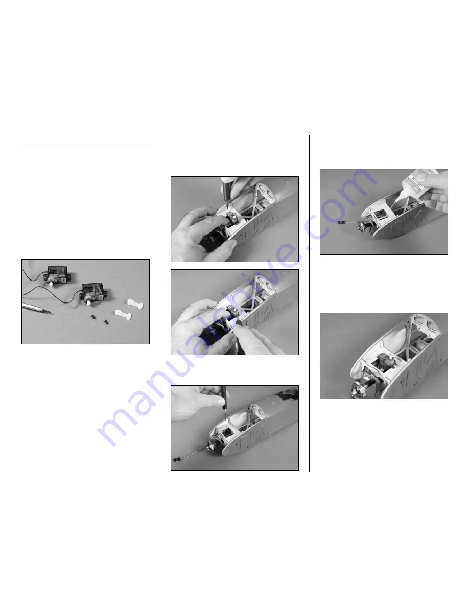
  1. Use a #0 Phillips screwdriver to remove the 

servo arms from the rudder and elevator servos.



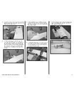
  2. Position the rudder servo in the opening at the 

front of the fuselage as shown. Slide the servo as 

far back in the opening as possible. Use a pencil to 

mark the position for the screws that will be used to 

secure the rudder servo.



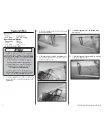
  3. Use a pin drill and 1/16-inch (1.5mm) drill bit 

to drill the holes for the two servo mounting screws.



  4. Apply 2–3 drops of thin CA into each of the 

holes to harden the surrounding wood. This is done 

to strengthen the wood and provide a stronger 

surface for the servo mounting screws.



  5. Position the rudder servo back in the opening 

in the front of the fuselage. Use a #1 Phillips 

screwdriver and the screws provided with the servo 

to secure the rudder servo. The lead from the servo 

will exit the hole in the bottom of the fuselage as 

shown.

Summary of Contents for Fokker DVII 250 Slow Flyer ARF

Page 1: ...tions Wingspan 34 0 in 865mm Wing Area 310 sq in 19 4 sq dm Length 26 5 in 672mm Weight w o Battery 7 20 7 50 oz 204 212 g Weight w Battery 8 50 9 00 oz 240 255 g Fokker DVII 250 Slow Flyer ARF Assemb...

Page 2: ...en matched with E flite s Park 250 brushless outrunner motor the Fokker DVII 250 s featherlight wing loading and stunning scale appearance make for a majestic slow flyer experience unlike any other Im...

Page 3: ...Direct Drive Prop EFLA1010 10 Amp Pro Brushless ESC EFLB0990 7 4V 800mAh 2 Cell Li Po JST Balance Optional Accessories EFLA110 Power Meter EFLC3005 Celectra 1 to 3 Cell Li Po Charger EFLC505 Intellig...

Page 4: ...ng them to their proper locations is not an issue 2 Locate the 6mm x 42mm carbon tube Follow the instructions included with the motor to glue using RTV silicone the motor to the motor tube Be careful...

Page 5: ...ods from the tubes in the fuselage at this time to keep them from sliding out and getting bent Both pushrods are the same length so returning them to their proper locations is not an issue 2 The motor...

Page 6: ...rewall as shown Speed Control Installation Required Parts Fuselage assembly Speed control Tie wrap not included Two sided tape 1 Mount the speed control using two sided tape to the front of the fusela...

Page 7: ...the servo as far back in the opening as possible Use a pencil to mark the position for the screws that will be used to secure the rudder servo 3 Use a pin drill and 1 16 inch 1 5mm drill bit to drill...

Page 8: ...at Steps 2 through 5 to install the elevator servo Note the direction of the output of the elevator servo 7 Use a pin drill and 1 16 inch 1 5mm drill bit to enlarge the outermost hole in the servo arm...

Page 9: ...ing gear is installed Stabilizer and Rudder Installation Required Parts Fuselage Stabilizer elevator Fin rudder Micro control horn 2 Micro control horn backplate 2 Required Tools and Adhesives Foam sa...

Page 10: ...ops of foam safe CA to the joint between the backplate and control horn to keep it secure for the life of your model 5 Repeat Steps 1 through 4 to install the control horn on the rudder Note the direc...

Page 11: ...hat the stabilizer is square to the fuselage by measuring from a center point on the fuselage to each stabilizer tip Use a hobby knife to enlarge the slots in the fuselage if any adjustments are requi...

Page 12: ...d fin in the neutral position 6 Turn on the transmitter and make sure the rudder stick and trim are centered Use a 1 Phillips screwdriver to tighten the 1 5mm machine screw that will secure the pushro...

Page 13: ...the propeller installed The plane could move and cause serious injury Always check the motor without the propeller to avoid injury 1 Slide the cowling on the fuselage Use the three screws removed fro...

Page 14: ...Bottom wing 2mm x 8mm wood screw 4 Required Tools and Adhesives Phillips screwdriver 1 1 Use a 1 Phillips screwdriver and four 2mm x 8mm wood screws to secure the bottom wing to the fuselage Ensure y...

Page 15: ...bane strut has been practiced mix a small amount of 30 minute epoxy and apply it to the ends of the strut Insert the strut in the fuselage as described previously Install both struts at this time Top...

Page 16: ...uired Tools and Adhesives Hobby knife with 11 blade Foam safe CA Low temp hot glue 1 Slide one of the wheels onto the landing gear The wheel should rotate freely on the gear If not use a hobby knife a...

Page 17: ...the cowling Press the gear in until fully seated making sure not to damage the fuselage in the process 6 You may find the gear is slightly loose when installed Use foam safe CA to glue the landing ge...

Page 18: ...rigging through a needle to make it easier to pass the rigging through the holes especially the tubes in the fuselage near the bottom wing Another option is to soak the last 4 inches 100mm of the rig...

Page 19: ...complete the first stage of rigging tie the rigging at the top of the strut as shown Use low tack tape to secure the tape on the underside of the bottom wing The end taped will be secured once the ri...

Page 20: ...down and through the forward tube in the fuselage This line will be in front of all the other rigging lines 14 After exiting the fuselage route the rigging up to the forward hole in the outer strut Ma...

Page 21: ...oint the rigging passes through the struts Allow the CA to fully cure before moving your model Don t forget to tie the ends that were taped to the bottom of the wing at this time as well 18 Use a smal...

Page 22: ...n the transmitter and receiver of your Fokker DVII 250 Slow Flyer Check the movement of the rudder using the transmitter When the stick is moved right the rudder should also move right Reverse the dir...

Page 23: ...that will help to establish a longer glide path and to make landings easier Before taxiing out to the runway double check all controls are working in the correct direction and functioning properly You...

Page 24: ...rections Warranty Information Warranty Period Exclusive Warranty Horizon Hobby Inc Horizon warranties that the Products purchased the Product will be free from defects in materials and workmanship at...

Page 25: ...ditional protection Ship via a carrier that provides tracking and insurance for lost or damaged parcels as Horizon is not responsible for merchandise until it arrives and is accepted at our facility A...

Page 26: ...hold waste disposal service or where you purchased the product Age Recommendation 14 years or over Not a toy Not intended for use by children without direct adult supervision 2009 Official Academy of...

Page 27: ...ndividuals properly licensed by the FCC are authorized to operate equipment on Amateur Band frequencies 6 I will not knowingly operate my model aircraft within three 3 miles of any preexisting flying...

Page 28: ...61822 USA 877 504 0233 Horizon Hobby UK Units 1 4 Ployters Rd Staple Tye Harlow Essex CM18 7NS United Kingdom 44 0 1279 641 097 Horizon Hobby Deutschland GmbH Hamburger Strasse 10 25335 Elmshorn Germ...

Reviews: