background image

22

E-flite Shoestring 15e ARF Assembly Manual

Cowling Installation

Required parts

Fuselage assembly  Cowling

Canopy 

Propeller

2mm x 6mm sheet metal screw (4)

Spinner backplate with adapter (not included)

Required Tools and Adhesives

Low-tack tape 

Thin CA

Pin vise 

Phillips screwdriver: #1

Hex wrench or ball driver: 3/32-inch

Open end or box wrench: 13mm

Drill bit: 1/32-inch (1mm), 5/64-inch (2mm)

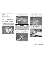
  1. Use a pin vise and 5/64-inch (2mm) drill bit 

to drill the four holes in the cowl for the mounting 

screws. Indentations in the cowl show where these 

holes should be drilled.

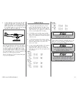
  2. Place the canopy back on the fuselage and 

attach the wings. Slide the cowl on the fuselage. 

You will need to flex the cowl to fit it over the 

landing gear fairings on the bottom of the fuselage.

Always balance your propeller. An unbalanced 

propeller can cause vibrations to be transmitted 

into the airframe, which could damage the 

airframe or other components as well as 

produce unwanted flight characteristics.

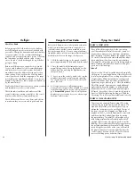
  3. Prepare the spinner assembly by sliding the 

propeller on the adapter shaft. Place the adapter 

nut on the shaft, but do not tighten it at this time. 

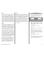
  4. Slide the propeller adapter and spinner 

backplate on the motor shaft. Check that the cowl 

is aligned with the spinner backplate. There should 

also be a 5/64 inch (2mm) gap between the 

backplate and cowl. Use two pieces of low-tack 

tape to hold the cowl in position on the fuselage. 

  6. Once aligned, use a pin vise and 1/32-inch 

(1mm) drill bit to drill through the holes in the cowl 

and into the fuselage.

Summary of Contents for Shoestring 15e ARF

Page 1: ...Shoestring 15e ARF Assembly Manual...

Page 2: ...use in order to operate correctly and avoid damage or serious injury Warnings Read and follow all instructions and safety precautions before use Improper use can result in fire serious injury and dam...

Page 3: ...urves of the front of the fuselage into one piece that stretches back to the mid canopy point This allows for very easy maintenance easy mounting of equipment and great cooling for the EP power system...

Page 4: ...0 AR7010 7 Channel DSMX Receiver SPMSA5030 Mini Digital Aircraft Servo 2 JRPS388 Digital Micro Metal Gear Servo 2 SPMA3001 6 inch 152mm Servo Extension 2 Recommended Sport Setup Motor Power 15 Brushle...

Page 5: ...will keep the servos from moving to their endpoints until the transmitter and receiver connect Landing Gear Installation Required Parts Fuselage Wheelpant right and left Landing gear fairing left and...

Page 6: ...eel using the shorter 4mm x 5mm button head screw and 4mm washer removed from the axle 7 Slide the wheel into the wheel pant You may need to flex the pant open slightly to get the wheel to fit 8 Use t...

Page 7: ...es when installed in the aileron 3 Place the hinges in the aileron as shown 4 Slide the aileron back into position When gluing the hinges do not use CA accelerator The CA must be allowed to soak into...

Page 8: ...not let the string fall into the wing as it is used to pull the servo lead through the wing 2 Install the rubber grommets and brass eyelets in the servo Place the servo between the tabs on the servo c...

Page 9: ...he center of the servo horn Remove the arms from the servo horn that will not be used using side cutters 8 Fit the servo horn to the servo so it is perpendicular to the servo Use side cutters to remov...

Page 10: ...of the aileron 14 Attach the control horn to the aileron using two 2mm x 12mm sheet metal screws and a control horn backplate Use a 1 Phillips screwdriver to tighten the screws 15 With the aileron se...

Page 11: ...levators 2 Use a pin vise and 1 16 inch 1 5mm drill bit to drill a hole in the center of each hinge slot Drill holes in both the elevators and stabilizer This creates a tunnel for the CA to wick into...

Page 12: ...stabilizer Use a square and felt tipped pen to mark the center line on the top of the stabilizer This will help in aligning the stabilizer on the fuselage later 8 Place a T pin in the center of each o...

Page 13: ...Phillips screwdriver 2 Epoxy brush Ruler Felt tipped pen Mixing cups Mixing sticks Paper towels T pin Low tack tape Rubbing alcohol Hobby knife with 11 blade 1 Remove the canopy from the fuselage by...

Page 14: ...r are in alignment with each other You might need to lightly sand the stabilizer saddle to bring the wing and stabilizer into alignment Check Alignment 9 After the stabilizer has been aligned trace th...

Page 15: ...ks Paper towels Rubbing alcohol Low tack tape Thin CA Pin vise Drill bit 1 16 inch 1 5mm T pins Phillips screwdriver 1 Hobby knife with 11 blade 1 Separate the rudder from the fin Set the hinges aside...

Page 16: ...bilizer 7 Use low tack tape to keep the fin in alignment with the stabilizer until the epoxy fully cures 8 Use a pin vise and 1 16 inch 1 5mm drill bit to drill a hole in the center of each hinge slot...

Page 17: ...s Fuselage assembly Servo with hardware 2 Receiver Receiver battery Transmitter Control horn 2 2mm x 12mm sheet metal screw 4 Control horn backplate 2 Hook and loop tape not included Required Tools an...

Page 18: ...This harder surface makes the screws more secure when installed 5 Return the servo to the fuselage Use a 1 Phillips screwdriver and the screws provided with the servo to secure it in the fuselage 6 Us...

Page 19: ...e control horn Adjust the clevis as necessary so the rudder is aligned with the fin when the rudder servo is centered Once aligned use needle nose pliers to tighten the nut against the clevis to keep...

Page 20: ...and loop tape Hook and loop strap Phillips screwdriver 2 Hex wrench or ball driver 2mm Power 25 or 2 5mm Power 15 Always use threadlock on metal to metal fasteners to prevent them from vibrating loos...

Page 21: ...results in the correct motor direction if using all E flite components 6 Connect the wires from the motor to the wires of the speed control Use a tie wrap not included to secure the leads so they don...

Page 22: ...ll need to flex the cowl to fit it over the landing gear fairings on the bottom of the fuselage Always balance your propeller An unbalanced propeller can cause vibrations to be transmitted into the ai...

Page 23: ...each hole to harden the surrounding wood This harder surface makes the screws more secure when installed 9 The cowl can now be secured to the fuselage using the four 2mm x 6mm sheet metal screws Tigh...

Page 24: ...vernight so the remaining water can evaporate Center of Gravity Required Parts Assembled airframe Required Tools and Adhesives Felt tipped pen Ruler Balancing stand optional An important part of prepa...

Page 25: ...Moving the elevator stick toward the bottom of the transmitter should make the airplane elevator move up 3 Check the movement of the ailerons with the radio system Moving the aileron stick right shou...

Page 26: ...Horizon Product Support office see addresses listed in the Warranty Services section of this manual or go to horizonhobby com to find a local Spektrum distributor in your country for service when usi...

Page 27: ...their racing line There is a tremendous amount of what we call bad air turbulence right behind and below them While it might seem cool and exciting to execute a pass below at these speeds there is rar...

Page 28: ...as the purchaser or user are not prepared to accept the liability associated with the use of the Product purchaser is advised to return the Product immediately in new and unused condition to the place...

Page 29: ...esignated collection point for the recycling of waste electrical and electronic equipment The separate collection and recycling of your waste equipment at the time of disposal will help to conserve na...

Page 30: ...ommission FCC Only individuals properly licensed by the FCC are authorized to operate equipment on Amateur Band frequencies 5 RC model aircraft will not operate within three 3 miles of any pre existin...

Page 31: ...31 E flite Shoestring 15e ARF Assembly Manual Building and Flying Notes...

Page 32: ...com E flite DSMX Celectra and the Horizon Hobby logo are trademarks or registered trademarks of Horizon Hobby Inc The Spektrum trademark is used with permission of Bachmann Industries Inc All other t...

Reviews: