18
E-flite Super Cub 25e ARF Assembly Manual
Stabilizer and Tail Bracing Installation
Required parts
Fuselage assembly Stabilizer (right and left)
2-56 x 6
1
/
2
-inch threaded rod (2)
2-56 x 6
3
/
4
-inch threaded rod (2)
4-40 x 5/8-inch socket head cap screw (3)
4-40 x 1/4-inch socket head cap screw (2)
4-40 lock nut (3)
Nylon brace end (8)
Carbon rod, 5
1
/
8
-inch (130mm)
Carbon rod, 3
9
/
16
-inch (90mm)
Required Tools and Adhesives
Pin vise
Drill bit: 7/64-inch (3mm)
Threadlock
Hex wrench: 3/32-inch
Toothpick
Nut driver: 1/4-inch
30-minute epoxy
Paper towel
Isopropyl alcohol
Square
Sandpaper
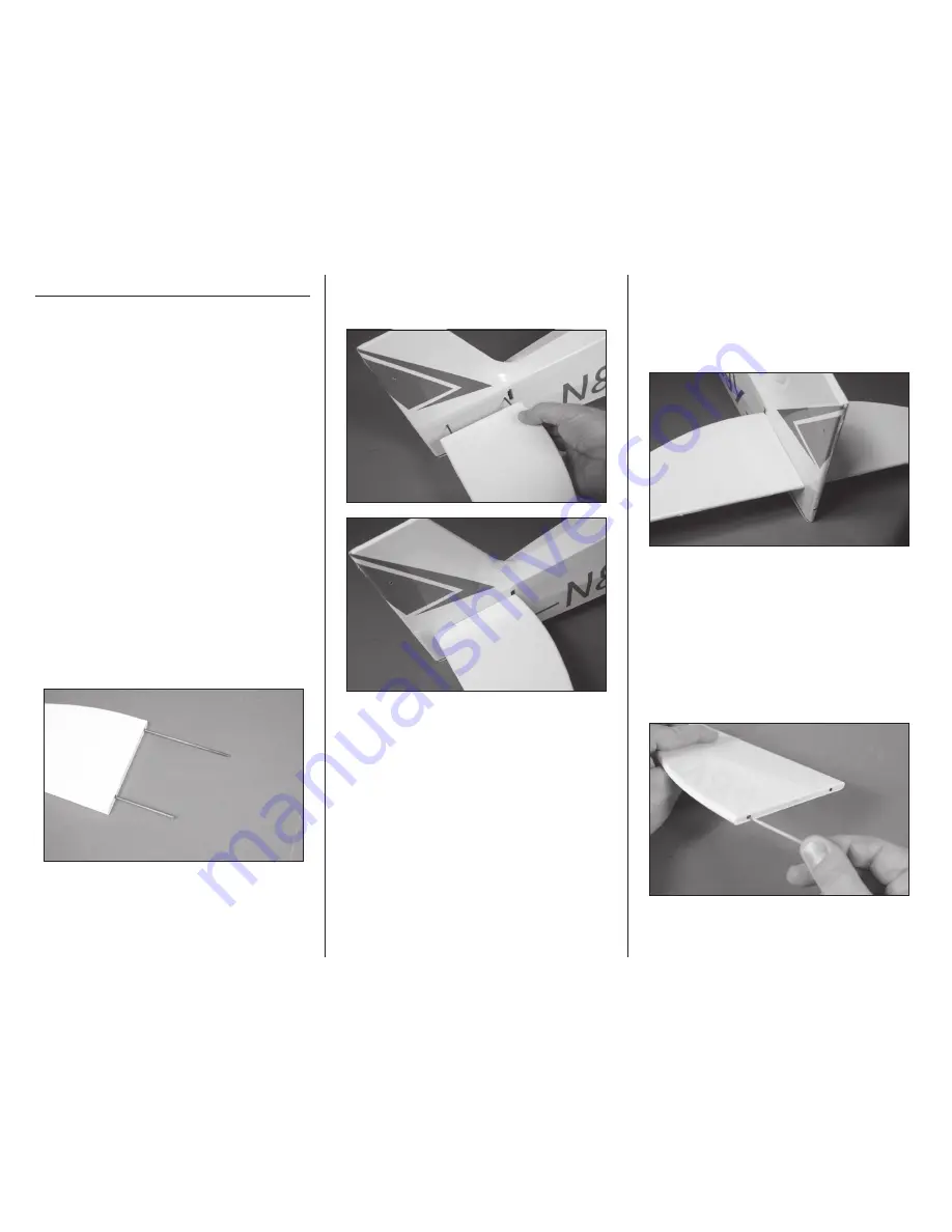
1. Slide the carbon fiber rods into the sockets in the
horizontal stabilizer. The longer 5
1
/
8
-inch (130mm)
rod is placed toward the front, while the shorter 3
9
/
16
-
inch (90mm) rod is positioned toward the trailing
edge. There are caps in the ends of the sockets for the
carbon rod spars. Do not force them in any farther
than they will easily slide.
2. Slide the stabilizer into position, guiding the
carbon rods through the holes in the fuselage. Slide
the stabilizer so it is tight against the fuselage.
3. Test the fit of the remaining stabilizer on the
stabilizer rods. Both stabilizers must fit snug against
the fuselage as shown. If not, determine the problem
and correct it before proceeding. Do not assume
that the rods are too long and shorten them. The
stabilizer relies on these for structural integrity.
4. Once the fit has been checked, remove the
stabilizers and carbon rods. Use sandpaper to
lightly sand each of the carbon rods. Mix a small
amount of 30-minute epoxy. Use a toothpick to
apply the epoxy in the holes for the carbon rods in
both stabilizer halves and the fuselage. Place the
stabilizers and carbon rods back into position and
allow the epoxy to fully cure before attaching the
bracing. Remove any excess epoxy before it cures
using a paper towel and isopropyl alcohol.


