33
Setting up for 3D flight
People often spend a tremendous amount of time
constructing a perfectly straight airplane only to
neglect the radio installation. The control system is
arguably of equal importance to actual construction
and must be given adequate attention to ensure that
the potential of the airplane is realized.
Since the purpose of the Tribute and Ultimate is 3D
flying, take a moment to think about what is actually
necessary for successful 3D flight. The first obvious
answer is thrust. In order to hover, the minimum
amount of thrust necessary is equal to the total weight
of the airplane. In reality we need to have some
excess thrust to maneuver and accelerate. For gas/
glow-powered models this typically is not a problem,
but many electric models are borderline in the static
thrust department. This is the primary reason that
the total weight of the airplane must be kept to a
minimum. The Tribute and Ultimate are designed to
have a flying weight under 12 ozs. The best way
to test to make sure you have adequate thrust for
hovering flight is to hold the airplane vertically and
advance the throttle to full power. The thrust should
be enough to make the airplane accelerate vertically
from a standstill.
Many people also consider the proverbial “aft”
center of gravity (CG) to be crucial to hovering
success. Through much experimentation on many
types of models, we have found that neither a very
forward or very aft CG is beneficial to hovering
flight. In fact, given sufficient control surface
movement, softened correctly with exponential
throws, one can hover controllably over a large
range of CG positions.
This brings us to the most important aspect of 3D
setup—control surface deflection. Do you need large
amounts of deflection to hover? The truth is you
do not. During the perfect hover or torque roll you
barely move the surfaces off their neutral position.
It is not until you get the airplane in an attitude far
enough from vertical that you need to delve into your
large reserves of control surface throw and excess
power. You will find that having 45–55 degrees of
throw is very beneficial to your success in 3D flight.
Typically, the most throw you can mechanically
achieve is what you should use. Set up the airplane
such that maximum throw is obtained by placing the
pushrod the farthest hole out on the servo and the
hole closest to the control surface on the control horn.
32
Center of Gravity
An important part of preparing the aircraft for flight
is properly balancing the model.
Caution: Do not inadvertently skip this step!
The recommended Center of Gravity (CG) location
for the Tribute™ is 4
1/4
" (108mm) behind the
leading edge of the wing against the fuselage. If
necessary, move the battery pack towards the nose
or the tail until the correct balance is achieved.
The Center of Gravity (CG) location for the Ultimate
is 3
3/4
" (95mm) behind the leading edge of the top
wing against the fuselage. Again, move the battery
pack to obtain the correct CG.
Note
: For best flight performance of the
Ultimate, a high center of gravity is important. To
achieve this, we recommend locating the battery
on the cabane strut even with the front edge.
Longitude Balance
Having a high thrust line and low vertical CG
position will cause the airplane to be less statically
stable during inverted flight, possibly requiring one to
hold up elevator to trim during inverted flight. With
this in mind, it is very important to balance the model
in a vertical sense. Do this by creating a small hole
directly behind the motor that passes through the
propeller thrust line. Insert a T-pin or small piece of
music wire through the hole and suspend the model.
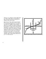
Be sure that the model hangs perfectly vertical as
shown below.

