3
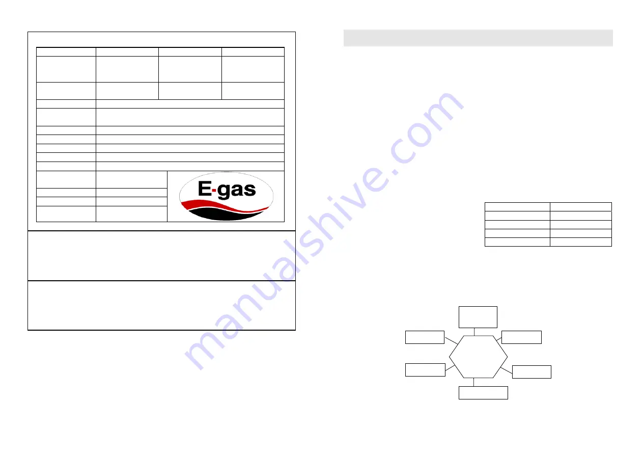
2.2 Main Technical Data & Features
Item Value Item
Value
Rated Thermal
Burden (kW)
24
Rated hot water
producing capacity
L/min (
Δ
t = 25 °C)
12
Working Voltage
(V.DC)
3 Power
Voltage
(V.DC) 3
Distributor:
E – Gas Systems
Appliance Model
& Size (mm)
JSD 12 E
819 x 395 x 245
Appliance Type B
B 11BS LPG Operating Pressure: 2.8 kPa
Certification Number:
I 1810
Type of Gas
G20 – 20 mbar
G31 – 37 mbar
Jet Size
0.67 mm
Gas Consumption
1.1 kg/hour
Nominal/minimum
Useful Output
P = 6.4 kW
Nominal Heat Input
Q = 16 kW
Max.
Water Pressure 7.5 bar
Min. Water Pressure: 0.25 bar
Features:
This model
has
accidental flameout safety device, vent pipe anti-block.
Must read the instruction manual before installing and using this appliance and operate it completely according
to the instruction manual.
Warning:
1. Read the technical instructions before installing the appliance.
2. Read the user’s instructions before lighting the appliance.
3. This appliance may only be installed in a room if the room meets the appropriate ventilation requirements.
2.3 Description of Control Functions
Winter/Summer Knob:
Used to switch from winter mode to summer mode or in a clockwise direction. If it
is in the summer mode, the gas diffusing into the main burner will be cut off and the energy of combustion
will decrease, in this way the gas will be saved in the summer mode.
Water Knob:
Used to switch between maximum water flow and minimum water flow.
Gas Knob: U
sed to switch between maximum gas and minimum gas feed.
4
3. INSTRUCTIONS FOR THE INSTALLER
3.1 Technical
Information
3.1.1
The installation, the adjustments and
maintenance listed in this part must only be carried
out by qualified installer. The manufacturer cannot be
held responsible for any damage to persons or things
deriving from an incorrect installation of the appliance.
3.1.2 The safety and automatic adjustment devices
of the appliance may only be modified or exchanged
by the manufacturer or duly authorised supplier.
The flue pipe anti-block device is a thermostat which
is fixed on the left side of flue outlet on the smoke
cover. When the flue pipe is blocked, the temperature
of the flue outlet will rise. After it is risen to a rated
value, the sensor in the thermostat will start to break
the circuit and cause the igniter stop. It must be
understood that the igniter is the main controller in the
machine, so if the circuit is broken, the
electromagnetic valve will stop working automatically,
and the ignition needle will also stop igniting. After
cleaning the flue pipe (we advise you to ask our after
sale service centre to help you), please press the
reset button to restart the sensor in the thermostat,
only in this way, it is safe to restart your gas water
heater.
3.2 Installation
3.2.1
Attention:
Water heater should be installed by
a registered gas appliance installer, carrying out the
installation in strict conformity to the manufacturer's
instructions and local bylaws to avoid any danger.
3.2.2 Position of Installation
INSTALL WATER HEATER OUTSIDE OF THE
BATHROOM
The water heater should be installed in an individual
room, separate from the bathroom and family living
room. Keep the room well ventilated so as to avoid
toxicosis by carbon monoxide. The air rate necessary
for discharge of combustion gas is listed as follow:
Heat Input ( kW)
Min Gas Output
(
v/s
)
≤
12 16
v/s
12~16 20
v/s
16~20 24
v/s
20~26 30
v/s
INSTALL IN A SEPARATE ROOM
NO
INSTALLATION
Stair and
safety exit
Cabinet
Bathroom
Living room
Bedroom
Basement


