background image

©2012 by e-Gizmo Mechatronix Central

N=L+"B"18"QR"7=L+0

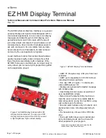
EZ HMI Display Terminal

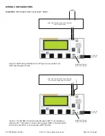
7.5-9.0V DC
DC INPUT

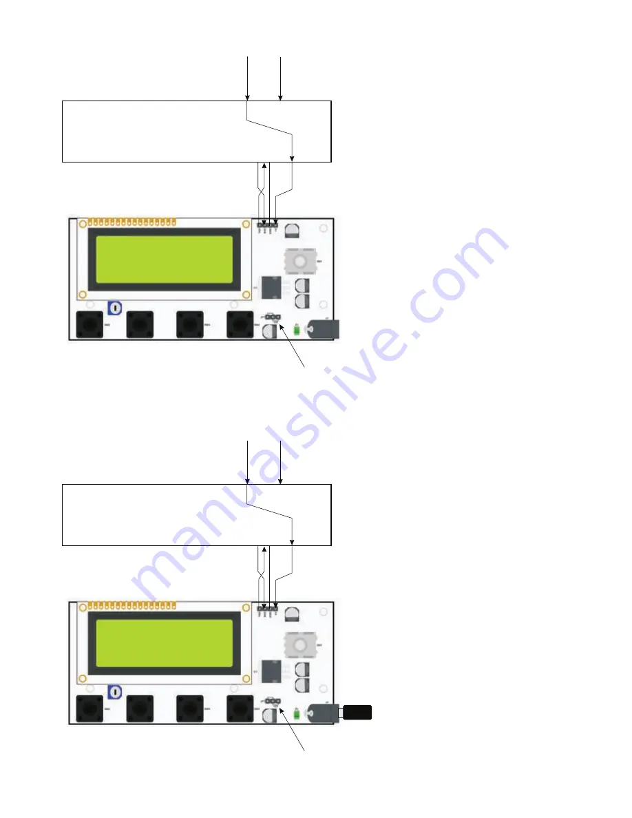
HOST CONTROLLER (MICROCONTROLLER)

with 3.0-3.3V Supply Voltage

TXD

VCC

RXD

GND

GND

NO JUMPER!

+3.0-3.3V

SOURCE

VCC

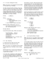
HOST CONTROLLER (MICROCONTROLLER)

with 5V Supply Voltage

TXD

VCC

RXD

GND

GND

+5V

SOURCE

VCC

JUMPER INSTALLED
ON JP1 5V POSITION

Figure 8. The EZ HMI, conversely, can be powered 
from a +5V sourced by the host controller circuit.

Figure 9. UART wiring interface to host controllers 
with 3.0-3.3V working logic levels. Make sure the 
jumper in JP1 is removed.

Summary of Contents for EZ HMI

Page 1: ...need to worry about you can put all your programming effort on the application project 0 1234 5 6 7 20 8 19 10 controller 71 197 3 1 AB CD E10 including Arduino gizDuino F 0 G 6 H5 27 0 I 1 7 0J 7 1...

Page 2: ...PORT ROTARY ENCODER SWITCH WITH PUSH FUNCTION EXT DC INPUT 7 5V 9V DC ENTER EXIT SELECT FUNCTION SWITCHES SW2 SW3 SW4 SW5 LCD CONTRAST ADJUST UART PORT POWER AUX DIO Figure 3 EZ HMI Controls and Port...

Page 3: ..._ NQ A N6aO 6 DO a NQ 20 33 K I 7 2 0 IB 71P 27 1 output and is used as follows no J1 DC input Ob EC 2 71P K 4 0 7734 2L IB 1 I 1 G 27 18 N6 T N1P 773 K 1 L Q I 0 0 IB 71P 01 41 2 0 1 71P 1 K F 0T D 2...

Page 4: ...LER MICROCONTROLLER with 5V Supply Voltage drawn from EZ HMI TXD RXD GND JUMPER INSTALLED ON JP1 5V POSITION 5V INPUT WIRING CONFIGURATIONS Important a 3 2L 0 9 0 21 c K Q C Figure 6 UART wiring inter...

Page 5: ...ND NO JUMPER 3 0 3 3V SOURCE VCC HOST CONTROLLER MICROCONTROLLER with 5V Supply Voltage TXD VCC RXD GND GND 5V SOURCE VCC JUMPER INSTALLED ON JP1 5V POSITION Figure 8 The EZ HMI conversely can be powe...

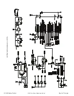
Page 6: ...2012 by e Gizmo Mechatronix Central Page 6 of 16 pages EZ HMI Display Terminal Figure 10 EZ HMI Schematic Diagram...

Page 7: ...r hence may be hard to read To minimize this adjust the LCD contrast until an acceptable scrolling display is obtained This may result in lower over 33 12 0 T 0 3 9 12 K1 0 21 7734 1 G displays 12 YTQ...

Page 8: ...5T5TQA 5T5T T 5T5TB C19 2 34 7 0 aB ekf 0P T 01 0 1 3K 77 g 0 710 12 of the alias 5T5TR 1 2 1K 0P 2 3 K 0 K character is displayed 5T5Th C19 2 34 7 0 aB ekf 0P T sor should jump to the next character...

Page 9: ...B N 00 a 1 2 1 2K c T Exit Selection Yes To save all changes to non volatile memory No To exit without saving to non volatile memory The edited data will remain in effect but will be reset to the last...

Page 10: ...de 3 2 Mode 1 Numeric Alphanumeric In this mode the input character set is divided into L 1 70 1 9 M 9 00 L 19710 12 0M easier The active input character set selection is in dicated by a single charac...

Page 11: ...2 2 d 0 8 2 12 07 g 1234 1 9 4 12 2 0 0 18 K 2 KK 12 1 8 2 12 07 g T End of transmission is signaled by the qO Xr9 M T q Xr and qO Xr K 7 M 9 M 0 2K 0 1 3K not be transmitted as literal string They sh...

Page 12: ...intable characters The three line implemen 12 H312L 2K 81 9 J 9 4 9 M 41 7 1L 9 longer but is more human readable Hence for clar ity all example codes given are shown in the long 81 9 T a 3 F 7 1 41 8...

Page 13: ...of the printing functions if you want to start print ing on any arbitrary position along the line 1 9 W q Xr1wqO Xr a W Py 0 9 00 L 7 1 QR 0 312L Example 1 Arduino G 073 4 e 912f 1 3 2 U 3TP HUcU5Jx S...

Page 14: ...K UJ to the brightest setting 1 9 W q XrBnnqO Xr a W 22 n v L 2 00 3 F 3 UAQi 07120 W H 1 W a 77 K P q Xr qO Xr O y 2F 3 K 3 F 3 6Z y K4 Example Arduino SDG M3 L L 2 00 1 B 3TP HUcU5Jx STX code 3T7 2...

Page 15: ...1K 7 00 K M 4 P 33 LL K 0 eQf 1234 8 0 2 K K 0 21 7 00 K K 2L 7 F 1 0 K Z 4 0 T 2 1 P1 K0 P 2 F M 4 0 7 00 K P 33 2 eQf 12 g 0 K Z 4 M 0 0 0 2 K Z 4 k 0 P 33 2 eUf F 2 8 KK 00 K M 4 9 2 K 7 00 KT 0 9...

Page 16: ...ions 1 9 W q XrSnqO Xr q XrRnqO Xr q XrInqO Xr a W 2 n 6 2 9 6 7 N1 U n NDY Q nNDB 5n NDR Input Port H a P M 7 33 7 21 9 334 eQfJ U n NDh Q n NGU 07120 W H 1 W a 77 K P q Xr qO Xr S R function 6Z A K4...

Reviews: