©2012 by e-Gizmo Mechatronix Central
Page 7 of 16 pages
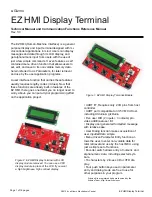
EZ HMI Display Terminal
1. DISPLAYING MESSAGE
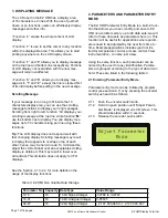
The LCD used in the EZ HMI has a display area
18"QR"<:=/=<;+/0"c"5"3.2+0T"a.;:";:+"-0+"18"d-0;":=38"
dozen or so functions, users can effortlessly display
messages and other info.
!")-2<;.12"e
c
” erases the whole content of LCD
display.
!")-2<;.12"e
>
” is use to set the cursor to any location
within the displayable area. This allows you to start
printing anywhere on the LCD display screen.
!")-2<;.12"e
1
f"=2K"e
2
” allows you to display message
on the top line and bottom line respectively. Portions
of LCD display not overwritten with the new mes-
sage will remain unaffected.
!")-2<;.12"e
3
f"=2K"e
4
”, allows you to display mes-
0=L+"=0".2"e
1
f"=2K"e
2
f*"+c<+7;";:+"3.2+".0"<3+=/+K"g/0;"
of its old display before putting in the new message.
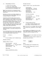
Scrolling Message
'8"41-/"9+00=L+".0";11"312L";1"g;".20.K+";:+"QR"
characters display area, you can use the scrolling
message functions to display your long messages.
]</133.2L"8/19"/.L:;";1"3+8;*"8-2<;.12"e
m
” displays your
0</133.2L"9+00=L+"=;";:+";17"3.2+*"P:.3+"8-2<;.12"e
M
”
use the bottom line to display. You can display mes-
0=L+0"-7";1"h^"<:=/=<;+/0"312L"7+/"3.2+"-0.2L";:+0+"
functions.
Tip:
The LCD display does not respond well with
8=0;"<:=2L.2L"K.073=4T"]</133.2L"9+00=L+"9=4"/+0-3;"
in display that appears to overlap on top of each
other, hence, may be hard to read. To minimize this,
adjust the LCD contrast until an acceptable scrolling
display is obtained. This may result in lower over-
=33"<12;/=0;T"&:.0"3.9.;=;.12"K1+0"21;"=7734";1"@)G"
displays.
]++";:+"]+<;.12"YTQ";1"YTY"81/"91/+"K+;=.30"12";:+"
usage of the display functions
2. PARAMETERS AND PARAMETER ENTRY
MODE
The EZ HMI Parameter Entry Mode is a built-in func-
tion that allows you to set, modify, and save to EZ
HMI non-volatile memory up to 48 data sets; we will
refer to these data sets as parameters here on. This
function will be useful for applications where param-
eters need to be adjusted by the user from time to
time. Example applications includes (and not lim-
ited to) temperature control, process control, timer,
instrumentation - to name just a few.
Using the same function, each parameter can be
2=9+K">4";:+"-0+/"81/"+=04".K+2;.g<=;.12T"N=/=9+
-
ters are grouped according to the type of data it can
:13KT"&:+0+"=/+"3.0;+K".2";:+"81331P.2L";=>3+"?T
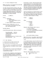
2.1 Entering Parameter Entry Mode
Parameter entry mode can be initiated by program
control (see section 4.7) or by pressing the encoder
switch push switch as follows:
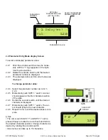
5TQTQ" N-0:";:+"+2<1K+/"0P.;<:"M21>T"
5TQT5" E13K".;".2"7-0:"710.;.12"-2;.3"e$Kd-0;"N=/=9
-
eter Mode” is displayed on LCD screen. This
0:1-3K";=M+"73=<+"P.;:.2"?"0+<12K0T
5TQT?" %+3+=0+";:+"+2<1K+/"7-0:"0P.;<:T
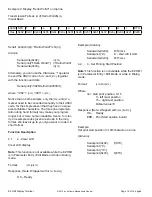
&=>3+"?T"Ob"EC'"[12"@13=;.3+"G=;="];1/=L+
Parameter No Capacity Data Type
Value Range
UAQB
16
QR">.;"].L2+K"'2;+L+/
A?5hRi";1"I?5hRh
QRA?Q
16
16 bit Unsigned Integer
UARBB?B
?5AYh
16
?5">.;"].L2+K"'2;+L+/
A"5*QYh*Yi?*RYi";1"I"5*QYh*Yi?*RYh
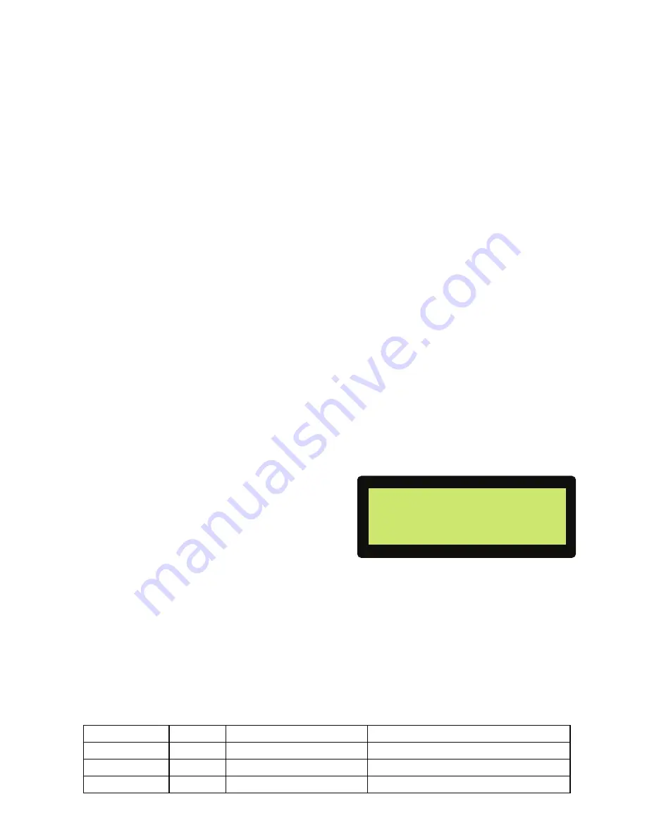
Adjust Parameter
Mode

