background image


61 


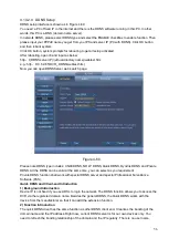
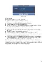
Figure 4-65 

 
4.10.2.8  FTP 

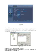
You need to download or buy FTP service tool (such as Ser-U FTP SERVER) to establish FTP service. 

Please install Ser-U FTP SERVER first. From 

“start” -> “program” -> Serv-U FTP Server -> Serv-U 

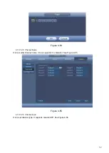
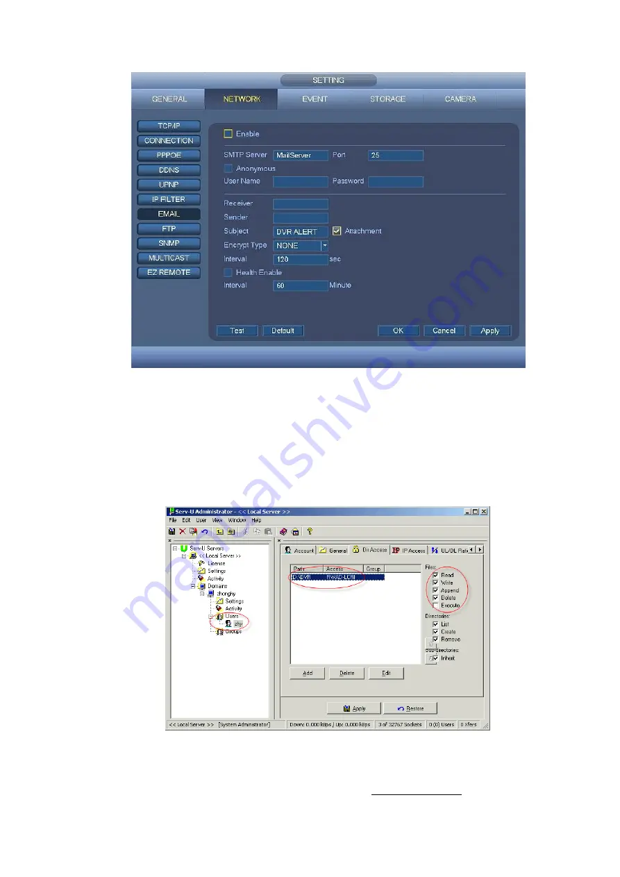
Administrator. Now you can set user password and FTP folder. Please note you need to grant write right 

to FTP upload user. See Figure 4-66. 


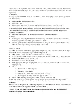
Figure 4-66 

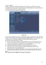
You can use a PC or FTP login tool to test setup is right or not. 

For example, you can login user ZHY to H140H140H140HTUFTP://10.10.7.7UTH   and then test it can 

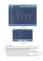
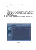
modify or delete folder or not.  See Figure 4-67.  

Summary of Contents for CJ-HDR104

Page 1: ...HD Analog Recorder User s Manual Model No CJ HDR104 CJ HDR108 Version 1 0 4...

Page 2: ...VERVIEW AND CONTROLS 4 2 1 Front Panel 4 2 1 1 CJ HDR104 CJ HDR108 4 2 2 Rear Panel 5 2 2 1 CJ HDR104 CJ HDR108 5 2 3 Connection Sample 6 2 3 1 CJ HDR104 CJ HDR108 6 2 4 Mouse Control 7 3 INSTALLATION...

Page 3: ...12 3 8 Other Interfaces 12 4 OVERVIEW OF NAVIGATION AND CONTROLS 13 4 1 Boot up and Shutdown 13 4 1 1 Boot up 13 4 1 2 Shutdown 13 4 1 3 Auto Resume after Power Failure 13 4 1 4 Replace Button Batter...

Page 4: ...4 5 13 USB Manager 29 4 6 USB Device Auto Pop up 29 4 7 Main Menu 29 4 8 Operation 30 4 8 1 Playback 30 4 8 2 Backup 37 4 8 3 Shut Down 39 4 9 Information 40 4 9 1 System Info 40 4 9 2 Event 43 4 9 3...

Page 5: ...8 2 Network 111 5 8 3 Event 123 5 8 4 Storage 128 5 8 5 General 131 5 9 Info 142 5 9 1 Version 142 5 9 2 Log 143 5 9 3 Online User 144 5 10 Playback 144 5 10 1 Playback Record 144 5 10 2 File List 145...

Page 6: ...v 6 FAQ 150 APPENDIX A HDD CAPACITY CALCULATION 155...

Page 7: ...designed to be a reference tool for the installation and operation of your system Here you can find information about this series DVR features and functions as well as a detailed menu tree Before ins...

Page 8: ...ualified engineers needed All the examination and repair work should be done by the qualified service engineers We are not liable for any problems caused by unauthorized modifications or attempted rep...

Page 9: ...rtation intelligent resident zone factory warehouse resources and water conservancy 1 2 Features This series product has the following features Real time monitor It has analog output port VGA port and...

Page 10: ...5 Support various decode protocols to allow the PTZ to control the speed dome Intelligent operation Mouse operation function In the menu support copy and paste setup function UPnP It is to establish t...

Page 11: ...era Blank Playback Backup Sync Playback 1 4 1 4 9 Search Mode Time Date MD Exact search accurate to second Playback Functions Play Pause Stop Rewind Fast play Slow play Next file Previous file Next ca...

Page 12: ...ontrols move up and down When device is in 1 channel playback mode use it to control playback control bar process Cancel ESC Go to previous menu or cancel current operation Close the top interface or...

Page 13: ...hreshold value or HDD being overwritten The light turns on to alert you please check HDD status at the GUI 2 2 Rear Panel 2 2 1 CJ HDR104 CJ HDR108 The 4 channel series rear panel is shown as below Se...

Page 14: ...able A You can connect to the control devices such as speed dome PTZ B RS485_B It is the cable B You can connect to the control devices such as speed dome PTZ 8 Network port 100M Ethernet port 9 HDMI...

Page 15: ...ment special control operation such as double click one item in the file list to playback the video In multiple window mode double left click one channel to view in full window Double left click curre...

Page 16: ...tection zone Select privacy mask zone Mouse rolling Normal mouse rolling operation in live view Rolling forward and backward for Channel or Window switching Click on Enlarge button in the Live View me...

Page 17: ...abel in the front panel is very important please check according to your purchase order The label in the rear panel is very important too Usually we need you to represent the serial number when we pro...

Page 18: ...button match or not We recommend you use UPS to guarantee steady operation DVR life span and other peripheral equipments operation such as cameras 3 5 Connecting Video Input and Output Devices 3 5 1 C...

Page 19: ...Keep it away from strong electromagnetic interference devices Using TV as video output device is not a reliable substitution method You also need to reduce the working hour and control the interferenc...

Page 20: ...ince RS485 is disabled by default for each camera you must enable the PTZ settings first This series DVRs support multiple protocols such as Pelco D Pelco P To connect PTZ devices to the DVR 1 Connect...

Page 21: ...e wait will display 4 1 2 Shutdown Note When you see corresponding dialogue box System is shutting down Do not click power on off button directly Do not unplug the power cable or click power on off bu...

Page 22: ...n interface See Figure 4 2 System consists of two accounts Username ADMIN Password 12345 administrator local and network Username default Password default hidden user Hidden user default is for system...

Page 23: ...eneral interface See Figure 4 3 For detailed information please refer to chapter 4 10 5 1 Figure 4 3 Click Next button you can go to Encode interface See Figure 4 4 For detailed information please ref...

Page 24: ...chedule interface See Figure 4 75 For detailed information please refer to chapter 4 10 4 1 Figure 4 5 Click Next button you can go to Record interface See Figure 4 76 For detailed information please...

Page 25: ...p wizard is complete See Figure 4 8 Figure 4 8 4 3 Manual Record 4 3 1 Live Viewing After you logged in the system is in live viewing mode You can see system date time channel name and window No If yo...

Page 26: ...digital zoom function Support real time backup function You can follow the contents listed below for the operation instruction Preview control interface Move you mouse to the top centre of the video o...

Page 27: ...tops recoridng You can find the record file on the flash disk 4 Manual Snapshot Click to snapshot 1 5 times The snapshot file is saved on the USB device or HDD You can go to the Playback interface cha...

Page 28: ...igure 4 13 Figure 4 13 Please refer to the following sheet for detailed information Item Note Period There are two periods in one day You can set different sharpness brightness and contrast setup for...

Page 29: ...t proper Please note the video may become hazy if the value is too low If this value is too high the dark section may lack brightness while the bright section may over exposure The recommended value r...

Page 30: ...rection arrows there is a 3D intelligent positioning key See Figure 4 15 Please make sure your protocol supports this function and you need to use mouse to control Click this key system goes back to t...

Page 31: ...eset Flip Tour Reset Pattern Aux Config Auto Scan Aux on off button Auto Pan Go to menu 4 4 2 1 PTZ Function Setup Click you can go to the following interface to set preset tour pattern and scan See F...

Page 32: ...add more presets to the tour Click Del preset button to remove it from the tour Please note some protocols do not support delete preset function Figure 4 19 Pattern Setup In Figure 4 17 click Pattern...

Page 33: ...Right button Now the scan setup process is complete Figure 4 21 4 4 2 2 Call PTZ Function Call Preset In Figure 4 16 input preset value and then click to call a preset Click again to stop call Call Pa...

Page 34: ...camera user s manual for Aux definition In some cases it can be used for special process Aux Config Click system goes to the following interface The options here are defined by the protocol The aux nu...

Page 35: ...ick button to go to the main menu interface 4 5 2 Output Screen Select corresponding window split mode and output channels 4 5 3 Tour Click button to enable tour the icon becomes you can see the tour...

Page 36: ...4 5 8 Playback Click button system goes to Playback interface Please refer to chapter Error Reference source not found 4 5 9 Alarm Status Click button system goes to alarm status interface It is to vi...

Page 37: ...backup and update Please refer to chapter 4 8 2 chapter 4 9 4 chapter Error Reference source not found and chapter 4 10 5 9 for detailed information 4 6 USB Device Auto Pop up After you inserted the...

Page 38: ...8 1 Playback Click Playback button in the main menu Playback interface is shown as below See Figure 4 29 Usually there are three file types R Regular recording file A External alarm recording file M M...

Page 39: ...d date means there is picture or file Otherwise there is no picture or file In any play mode click the date you want to see you can see the corresponding record file trace in the time bar 4 Playback t...

Page 40: ...ed file Click the button to view the locked file Return Click button system goes back to the calendar and channel setup interface Please note For the file that is writing or overwriting it cannot be l...

Page 41: ...record The time bar is beginning with 0 o clock when you are setting the configuration The time bar zooms in the period of the current playback time when you are playing the file 11 Backup Select the...

Page 42: ...ther channel synchronization switch to play when playback When playing the file click the number button system can switch to the same period of the corresponding channel to play 16 Digital zoom When t...

Page 43: ...rner to search records by time See image on the left side of the Figure 4 31 For example input time 14 00 00 and then click Search button you can view all the record files after 14 00 00 The records i...

Page 44: ...important video information Add Mark When system is playback click Mark button you can go to the following interface See Figure 4 32 Figure 4 32 Playback Mark During 1 window playback mode click mark...

Page 45: ...nly change mark name here Delete Here you can select the mark information item you want to delete and then click Delete button you can remove one mark item Note After you go to the mark management int...

Page 46: ...d its total space and free space The device includes CD RW DVD burner USB device flash disk eSATA backup Figure 4 34 Select backup device and then set channel file start time and end time Click add bu...

Page 47: ...ile name the YDM format is Y M D H M S File extension name is dav Tips During backup process you can click ESC to exit current interface for other operation The system will not terminate backup proces...

Page 48: ...em information There are total four items HDD Info hard disk information record info BPS data stream statistics version See Figure 4 38 Figure 4 38 4 9 1 1 HDD Information Here is to list hard disk ty...

Page 49: ...ce The HDD total capacity Free space The HDD free capacity Status HDD can work properly or not SMART Display HDD information See Figure 4 39 Figure 4 39 Double click on HDD information you can see the...

Page 50: ...9 1 2 Record Info It is to view record start time and end time See Figure 4 41 Figure 4 41 4 9 1 3 BPS Here is for you to view current video data stream KB s resolution and etc See Figure 4 42 Figure...

Page 51: ...re is for you to view some version information such as version number built date serial number and etc See Figure 4 43 Figure 4 43 4 9 2 Event It is to display device status and channel status See Fig...

Page 52: ...leted user in each five seconds and refresh the list automatically Figure 4 45 4 9 3 2 Network Load Network load is shown as in Figure 4 46 Here you can view the follow statistics of the device networ...

Page 53: ...peripheral device Click Browse button to select the snap path The steps here are same as preview backup operation You can view all connected network adapter names including Ethernet PPPoE WIFI and 3G...

Page 54: ...nd time then click search button You can view the log files in a list System max displays 100 logs in one page It can max save 1024 log files Please use page up down button on the interface or the fro...

Page 55: ...47 Figure 4 48 Select an item on the list and then double click the log item you can view the detailed information such as log time log type log user IP address and etc See Figure 4 49 Figure 4 49...

Page 56: ...ranges from 40 to 60 Contrast It is to adjust monitor window contrast The value ranges from 0 to 100 The default value is 50 The larger the number is the higher the contrast is You can use this funct...

Page 57: ...series Frame rate It ranges from 1f s to 30f s in NTSC mode and 1f s to 25f s in PAL mode Bit rate type System supports two types CBR and VBR In VBR mode you can set video quality I Frame Interval He...

Page 58: ...ng and trigger If you set timing mode you need to set snapshot frequency If you set trigger snapshot you need to set snapshot activation operation Image size Here you can set snapshot picture size Qua...

Page 59: ...means the privacy mask zone can not be viewed by user when system is in preview status Cover area Here is for you to set cover area You can drag your mouse to set proper section size Or you can use t...

Page 60: ...re 4 54 4 10 1 2 4 Channel Name It is to modify channel name It max supports 31 character See Figure 4 55 Figure 4 55 4 10 1 2 5 Channel Type It is to set channel type It supports coaxial UTP See Figu...

Page 61: ...can reduce packets and enhance network transmission efficiency The following MTU value is for reference only 1500 Ethernet information packet max value and it is also the default value It is the typi...

Page 62: ...t is to say the specified length of the subnet prefix shall have the same string Preferred DNS server DNS server IP address Alternate DNS server DNS server alternate address After completing all the s...

Page 63: ...PPPoE password which you get from your ISP Internet service provider Click save button you need to restart to activate your configuration After rebooting DVR will connect to internet automatically The...

Page 64: ...S type includes CN99 DDNS NO IP DDNS Quick DDNS Dyndns DDNS and Private DDNS All the DDNS can be valid at the same time you can select as you requirement Private DDNS function shall work with special...

Page 65: ...email before the cancel operation if your email address setup is OK 4 10 2 5 UPnP The UPNP protocol is to establish a mapping relationship between the LAN and the WAN Please input the router IP addre...

Page 66: ...nabled trusted sites function only the IP listed below can access current DVR If you enable blocked sites function the following listed IP addresses can not access current DVR Enable Select the checkb...

Page 67: ...nd end address if you add IP section and the end address shall be larger than the start address f System may check newly added IP address exists or not System does not add if input IP address does not...

Page 68: ...rval The send interval ranges from 0 to 3600 seconds 0 means there is no interval Health Enable Please select the checkbox to enable this function This function allows the system to send out the test...

Page 69: ...m Serv U FTP Server Serv U Administrator Now you can set user password and FTP folder Please note you need to grant write right to FTP upload user See Figure 4 66 Figure 4 66 You can use a PC or FTP l...

Page 70: ...User name and password is the account information for you to login the FTP File length is upload file length When setup is larger than the actual file length system will upload the whole file When se...

Page 71: ...ully connection Please follow the steps listed below to configure In Figure 4 69 select the checkbox to enable the SNMP function Input the IP address of the PC than is running the software in the Trap...

Page 72: ...4 0 0 0 224 0 0 255 TTL 1 When sending out telegraph For example 224 0 0 1 All systems in the sub net 224 0 0 2 All routers in the sub net 224 0 0 4 DVMRP router 224 0 0 5 OSPF router 224 0 0 13 PIMv2...

Page 73: ...oss tampering The video loss has no detection region and sensitivity setup and tampering has no detection region setup You can see motion detect icon if current channel has enabled motion detect alarm...

Page 74: ...anti dither time refers to the alarm signal lasts time It can be seem as the alarm signal activation stays such as the buzzer tour PTZ activation snapshot channel record The stay time here does not i...

Page 75: ...he checkbox to select the corresponding function After all the setups please click OK button system goes back to the previous menu Note In motion detection mode you can not use copy paste to set chann...

Page 76: ...68 Figure 4 74 Figure 4 75...

Page 77: ...the type list You can see the interface is shown as in Figure 4 77 This function allows you to be informed when video loss phenomenon occurred You can enable alarm output channel and then enable show...

Page 78: ...attern activation operation when video loss occurs Please refer to chapter 4 10 3 1 1 motion detection for detailed information Note In Detect interface copy paste function is only valid for the same...

Page 79: ...e message in the local screen to alert you when alarm occurs Alarm upload System can upload the alarm signal to the network including alarm centre if you enabled current function For disconnection eve...

Page 80: ...72 Figure 4 79 Figure 4 80...

Page 81: ...hour regular mode You can set record type and time in schedule interface In the main menu from Setting Storage Schedule you can go to schedule menu See Figure 4 85 Please note you need to go to main m...

Page 82: ...dundancy System supports redundancy backup function You can select the checkbox to activate this function Please note before enable this function please set at least one HDD as redundant Main menu Set...

Page 83: ...ere are color bars for your reference Green color stands for regular recording yellow color stands for motion detection and red color stands for alarm recording The white means the MD and alarm record...

Page 84: ...unction In the main menu from Setting Storage HDD Manage you can set one or more disk s as redundant You can select from the dropdown list System auto overwrites old files once hard disk is full Pleas...

Page 85: ...snapshot function of corresponding channels See Figure 4 88 In main menu from Setting Camera Encode Snapshot interface here you can input snapshot mode as timing image size quality and snapshot freque...

Page 86: ...78 Figure 4 89 Figure 4 90...

Page 87: ...tem can snapshot when the corresponding alarm occurred In main menu from Setting Camera Encode Snapshot interface here you can input snapshot mode as trigger image size quality and snapshot frequency...

Page 88: ...ccurs and otherwise system just operates the schedule snapshot 4 10 4 1 2 4Image FTP In the main menu from Setting Network FTP you can set FTP server information Please enable FTP function and then cl...

Page 89: ...rd disk management See Figure 4 94 You can see current HDD type status capacity and etc The operation includes format HDD and change HDD property read and write read only redundancy Figure 4 94 Please...

Page 90: ...n the front panel System supports main stream and sub stream There are three statuses schedule manual stop See Figure 4 95 Please select the icon to select corresponding channel Manual The highest pri...

Page 91: ...ll languages listed here are optional Slight difference maybe found in various series Video standard There are two formats NTSC and PAL HDD full Here is for you to select working mode when hard disk i...

Page 92: ...herwise it will go to the login interface Mouse sensitivity You can set the speed via dragging the slide bard You can Click Default button to restore default setup Figure 4 97 4 10 5 1 2 Date and Time...

Page 93: ...Note When you enable Holiday settings and schedule setup at the same time holiday setting has the priority If the selected day is a holiday then system records as you set in holiday setting If it is n...

Page 94: ...86 Figure 4 99 Figure 4 100...

Page 95: ...urrent setup Transparency Here is for you to adjust transparency The value ranges from 0 to 100 Time display You can select to display time or not when system is playback Channel display You can selec...

Page 96: ...play all channel groups on current split mode You can edit and delete a channel group here Double click an item in the list you can edit its channel group setup Right now system max supports 32 Add Un...

Page 97: ...ay vary due to different device capabilities Please select from the dropdown list Frame rate The frame rate value may vary due to different device capabilities Please select from the dropdown list Bit...

Page 98: ...VI The control signal is sent to the PTZ via the coaxial cable For the serial mode the control signal is sent to the PTZ via the RS485 port Protocol Please select corresponding protocols such as HD CV...

Page 99: ...network The network type interface is shown as below See Figure 4 106 Here we take the ATM POS protocol to continue There are two types with or without the protocol according to client s requirements...

Page 100: ...Add group Modify group Modify password For account management please note For the user account name and the user group the string max length is 6 byte The backspace in front of or at the back of the s...

Page 101: ...When you add a new user you can input the MAC address of current user Only the user of the same MAC address can access the device remotely MAC address is for the device of the same LAN If you leave MA...

Page 102: ...4 110 Here you can input group name and then input some memo information if necessary There are total 15 rights such as account system offline user default upgrade PTZ info manual control backup colo...

Page 103: ...corresponding MAC address of current user If you leave this item in blank any MAC address user can share this user account to login Please note system needs to check the validity of MAC Only the 12 di...

Page 104: ...first You can see a dialogue box asking you to select a folder if you are selecting a file System pops up a dialogue box if there is no configuration file under current folder After successfully impo...

Page 105: ...lt icon system pops up a dialogue box You can select the checkbox to restore default factory setup See Figure 4 114 All General Network Event Storage Camera Please select the checkbox to select the co...

Page 106: ...u can go to the following interface See Figure 4 115 Upgrade Please insert the USB device that have the update file to the device and then click the Upgrade button to begin the upgrade process Importa...

Page 107: ...as Safari Firefox browser Google browser Device supports multiple channel monitor PTZ control DVR parameter setup on the Apple PC 5 2 Login Open IE and input DVR address in the address column For exam...

Page 108: ...unction buttons Live chapter 5 4 Playback chapter 5 10 Alarm chapter 5 11 Setup chapter 5 8 Info chapter 5 9 and Logout chapter 5 12 Section 2 There are channel numbers Section 3 Open all button is to...

Page 109: ...t end is using the first channel audio input port During the bidirectional talk process system will not encode the audio data from the 1 channel Figure 5 6 Section 5 Instant record button Click it the...

Page 110: ...button and then left drag the mouse in the zone to zoom in right click mouse system restores original status 2 Record When you click local record button the system begins recording and this button bec...

Page 111: ...wn list Input preset value in the column Click Add preset button you have added one preset in the tour Repeat the above procedures you can add more presets in one tour Or you can click delete preset b...

Page 112: ...to restore system default setup Figure 5 12 5 7 WAN Login In WAN mode after you logged in the interface is shown as below See Figure 5 13 Figure 5 13 Please refer to the following contents for LAN an...

Page 113: ...not support alarm activation to open the video function in the Alarm setup interface Important For multiple channel monitor mode system adopts extra stream to monitor by default You can not modify ma...

Page 114: ...value is too high The value ranges from 0 to 100 The recommended value ranges from 40 to 60 Contrast It is to adjust monitor window contrast The value ranges from 0 to 100 The default value is 50 The...

Page 115: ...is the clearer the video is But the noise may become large too 2D NR It is to process the noise of the single image The video may become soft after process The larger the value is the better the effe...

Page 116: ...the bit rate is the better the quality is Please refer to recommend bit rate for the detailed information Sub stream In CBR the bit rate here is the max value In dynamic video system needs to low fram...

Page 117: ...ct alarm tampering alarm or local activation alarm occurs Image size Image size supports D1 HD1 2CIF and CIF Quality It is to set the image quality There are six levels Snapshot Frequency It is to set...

Page 118: ...k video Time Display You can enable this function so that system overlays time information in video window You can use the mouse to drag the time title position You can view time title on the live vid...

Page 119: ...mode to auto search the IP If you select the static mode you need to set the IP submask gateway manually If you select the DHCP mode you can view the IP submask gateway from the DHCP If you switch fr...

Page 120: ...put value shall be 128 digit It shall not be left in blank LAN Download System can process the downloaded data first if you enable this function The download speed is 1 5X or 2 0X of the normal speed...

Page 121: ...ovider and enable PPPoE function Please save current setup and then reboot the device to get the setup activated Device connects to the internet via PPPoE after reboot You can get the IP address in th...

Page 122: ...other DDNS client end It realizes the bonding of the domain name and the IP address Right now current DDNS server is for our own devices only You need to refresh the bonding relationship of the domain...

Page 123: ...ess setup is OK 5 8 2 6 IP filter The IP filter interface is shown as in Figure 5 27 After you enabled trusted sites function only the IP listed below can access current DVR If you enable blocked site...

Page 124: ...il immediately when the alarm occurs When the alarm motion detection or the abnormality event activates the email system sends out the email according to the interval you specified here This function...

Page 125: ...the Network Services from the Windows Components Wizard Click the Details button and then select the Internet Gateway Device Discovery and Control client and UPnP User Interface Please click OK to beg...

Page 126: ...e SNMP allows the communication between the network management work station software and the proxy of the managed device It is reserved for the 3rd party to develop Figure 5 31 Please refer to the fol...

Page 127: ...e ranges from 1 to 165535 The default value is 162 SNMP version Select V1 system only processes the information of V1 Select V2 system only processes the information of V2 5 8 2 11 Multicast The multi...

Page 128: ...etc Click Create button See Figure 5 34 Note Please make sure the IP or domain information is the same as your device IP or domain name Figure 5 34 You can see the corresponding prompt See Figure 5 35...

Page 129: ...following interface See Figure 5 37 Figure 5 37 Click Install certificate button you can go to certificate wizard See Figure 5 38 Figure 5 38 Click Next button to continue Now you can select a locati...

Page 130: ...39 Click Next button you can see the certificate import process is complete See Figure 5 40 Figure 5 40 Click Finish button you can see system pops up a security warning dialogue box See Figure 5 41...

Page 131: ...TTPS default value is 443 Figure 5 43 5 8 2 12 4 Login Open the browser and then input http xx xx xx xx port xx xx xx xx is your device IP or domain mane Port is your HTTPS port If you are using defau...

Page 132: ...124 Figure 5 44 Figure 5 45 Figure 5 46...

Page 133: ...nterface is shown as in Figure 5 46 Here you can set motion detection zone There are four zones for you to set Please select a zone first and then left drag the mouse to select a zone The correspondin...

Page 134: ...centre Buzzer Select the checkbox here to enable this function The buzzer beeps when an alarm occurs 5 8 3 1 2Video Loss The video loss interface is shown as in Figure 5 48 After analysis video syste...

Page 135: ...27 Figure 5 49 5 8 3 2 Abnormality It includes two types HDD Error and Network Error See Figure 5 50 and Figure 5 51 Figure 5 50 Figure 5 51 Please refer to the following sheet for detailed informatio...

Page 136: ...Email If you enabled this function System can send out an email to alert you when an alarm occurs Alarm upload System can upload the alarm signal to the centre Including alarm centre Buzzer Select the...

Page 137: ...checkbox here to enable redundancy function Please note this function is null if there is only one HDD Setup Sunday to Saturday Click the Setup button you can set record period See Figure 5 53 There...

Page 138: ...f channel 1 to all channels you can click the first box ALL Click the OK button to save current copy setup Click the OK button in the Encode interface the copy function succeeded 5 8 4 2 HDD Manage Th...

Page 139: ...ecord no matter what period applied in the record setup Stop Stop current channel record no matter what period applied in the record setup Start all stop all Select the corresponding All button you ca...

Page 140: ...or you to specify record duration The value ranges from 1 to 120 minutes Default value is 60 minutes Auto Logout Here is for you to set auto logout interval once login user remains inactive for a spec...

Page 141: ...e week format NTP You can select the checkbox to enable NTP function NTP server You can set the time server address Port It is to set the time server port Interval It is to set the sync periods betwee...

Page 142: ...s for you to adjust transparency The value ranges from 0 to 100 TimeDisplay Channel Display Select the checkbox here you can view system time and channel number on the monitor video Image enhance Sele...

Page 143: ...responding information Figure 5 62 Please refer to the following sheet for detailed information Parameter Function Enable Select the checkbox here to enable Zero Channel function Compression System su...

Page 144: ...up here shall comply with your dome address otherwise you can not control the speed dome Baud Rate Select the dome baud rate Default setup is 9600 Data Bit Default setup is 8 Please set according to t...

Page 145: ...e is shown as in Figure 5 65 Source IP refers to host IP address that sends out information usually it is the device host Destination IP refers to other systems that receive information Usually you do...

Page 146: ...d in only one group 5 8 5 5 1User In this interface you can add remove user and modify user name See Figure 5 66 Figure 5 66 Add user It is to add a name to group and set the user rights See Figure 5...

Page 147: ...modify the user password You need to input the old password and then input the new password twice to confirm the new setup Please click the Save button to save Please note the password ranges from 1...

Page 148: ...et its corresponding rights See Figure 5 70 Please input the group name and then select the checkbox to select the corresponding rights It includes shutdown reboot device live view record control PTZ...

Page 149: ...elect auto reboot and auto delete old files interval from the dropdown list If you want to use the auto delete old files function you need to set the file period Click Manual reboot button you can res...

Page 150: ...74 5 8 5 9 Upgrade The upgrade interface is shown as in Figure 5 75 Please select the upgrade file and then click the update button to begin update Please note the file name shall be as bin During th...

Page 151: ...end time of the requested log Type Log types include system operation configuration operation storage operation alarm operation record operation account management log clear and playback Search You c...

Page 152: ...78 5 10 Playback Click Playback button you can see an interface is shown as in Figure 5 79 Figure 5 79 5 10 1 Playback Record Please set record type record date window display mode and channel name Se...

Page 153: ...e corresponding files in the list See Figure 5 82 Figure 5 82 5 10 3 Playback Select a file you want to play double click on the selected file for system to begin playback You can select to playback i...

Page 154: ...want to download and then click download button you can see an interface shown as in Figure 5 84 The Download button becomes Stop button and there is a process bar for your reference Please go to you...

Page 155: ...tart time and end time Click Search button the download by file interface is shown as in Figure 5 85 Figure 5 85 5 10 5 2 Download by Time Select channel bit stream type start time and end time Click...

Page 156: ...ou can see an interface is shown as Figure 5 88 Here you can set device alarm type and alarm sound setup Please make sure you have enabled audio function of corresponding alarm events Figure 5 88 Plea...

Page 157: ...Sound Play alarm sound System sends out alarm sound when an alarm occurs You can specify as you wish Sound path Here you can specify alarm sound file 5 12 Log out Click log out button system goes back...

Page 158: ...h too much dust Hardware malfunction 3 System can not detect hard disk There are following possibilities HDD is broken HDD ribbon is damaged HDD cable connection is loose Main board SATA port is broke...

Page 159: ...a power picker It is not a power acoustics Audio cable is damaged DVR hardware malfunctions 9 There is audio when monitor but there is no audio when system playback There are following possibilities S...

Page 160: ...No dx8 1 or higher Please upgrade display card driver Network connection error Network setup error Password or user name is invalid Client end is not compatible with DVR program 14 There is only mosai...

Page 161: ...There are following possibilities Alarm setup is not correct Alarm cable connection is not correct Alarm input signal is not correct There are two loops connect to one alarm device 20 Record storage p...

Page 162: ...regularly The device shall be soundly earthed in case there is audio video disturbance Keep the device away from the static voltage or induced voltage Please unplug the power cable before you remove t...

Page 163: ...ing to Formula 3 to calculate total capacity accumulation T q that is needed for all channels in the DVR during scheduled video recording c i i T m q 1 3 In the formula c means total number of channel...

Page 164: ...nd Intel Core are trademarks of Intel Corporation in the U S and other countries Adobe Acrobat Reader and Reader are either registered trademarks or trademarks of Adobe Systems Incorporated in the Uni...

Reviews: