CLASS 3400 METER
62-0391-03
14
WARNING
Failure to attach the protective earth ground wire securely to the meter
creates a potential shock hazard. Do not operate the meter without a
protective earth ground connection securely installed.
3.
Wire Entry:
CL3400 meters are supplied with two 3/4” conduit K.O.s on the bottom of the 4X
enclosure for all wiring. The Type1 enclosures are supplied with three 3/4” con-
duit K.O.s.
Route the appropriate cabling to and through the respective enclosure opening.
After installing the conduit fitting and conduit, verify that each conduit slip nut is
securely tightened to its respective conduit fitting. Any unused openings must be
sealed with a UL rated plugging device suitable for the rating of the enclosure.
4.
Unit MAINS Wiring:
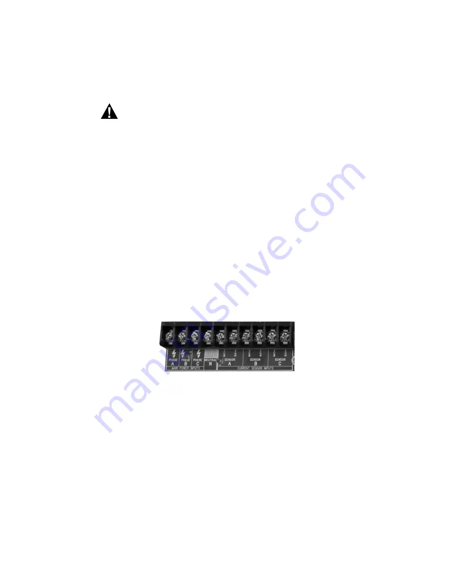
The first four positions of terminal block TB1, located at the bottom left corner of
the main power board, are clearly labeled Phase A, B, C, N (neutral). Earth
Ground MUST be connected to the PCB mounting screw in the lower right cor-
ner.
Connect the NEUTRAL wire to the appropriate terminal block position.
Fig. 4. Terminal Block TB1.
NOTE: For 3-wire delta-type applications, do NOT connect the neutral wire.
Remove the terminal block screw for this position.
a. Connect the NEUTRAL wire to the appropriate terminal block position.
b. Earth Ground: Connect the Earth Ground to the PCB mounting screw in the
lower right corner.
c. External Switch Mechanism/In-Line Fuse Installation
To ensure a safe installation, the Class 3400 meter requires an external
switch mechanism, such as a circuit breaker, be installed on the meter’s
MAINS input wiring. The switch mechanism must be installed in close prox-


