Final Test Procedures 12–2
4.
Use a regulated low pressure line or hand pump to pressurize the motor cavity to 5
psi and look for bubbles. Bubbles from the discharge elbow indicate a seal leak and
bubbles from around the motor head/motor housing joint indicate a motor housing
O-ring leak.
5.
If this test is being performed on a unit during disassembly, turn the assembly
upside down and remove the hose from the test fitting. Look for water escaping
from the motor cavity. If water is noted, the motor will need new bearings and the
windings will need to be cleaned, dried and tested.
6.
Bleed off the air pressure before reassembly.
Control Cavity Leak Test
The pump must be assembled completely in order to perform this test. This test is also
performed before disassembly to check for leaks.
1.
Use a regulated low pressure line or hand pump to pressurize the motor cavity to
5 psi. Spray soapy water on fittings and joint. Look for bubbles where the control
housing and the motor housing join together, and the power cable entry point. Failure
to repair leaks will result in premature failure of the unit.
2.
Remove the test fitting. Apply Loctite 598 generously to the threads of the air release
plug and install it. Apply Loctite 598 over the plug after it is installed; apply more, if
necessary, to cover the plug.
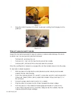
Figure 12-3
Figure 12-4
Summary of Contents for Extreme Series
Page 1: ...Service Manual E One Extreme Grinder Pumps 240V 60 Hz Hardwired Controls...
Page 2: ......
Page 32: ...Pump End 5 8 Figure 5 9a D Series Pump Exploded View...
Page 33: ...Pump End 5 9 Figure 5 9b W Series Pump Exploded View...
Page 34: ...Pump End 5 10 Figure 5 9c Gatorgrinder GH Series Pump Exploded View...
Page 35: ...Pump End 5 11 Figure 5 9d IH091 Pump Exploded View...
Page 36: ...Pump End 5 12...
Page 58: ...Level Sensor 8 10 Figure 8 35 Level Sensor Assembly Exploded View all hardwired pumps...
Page 70: ...Mechanical Seal Assembly 11 2...
Page 75: ......


