49
07/10
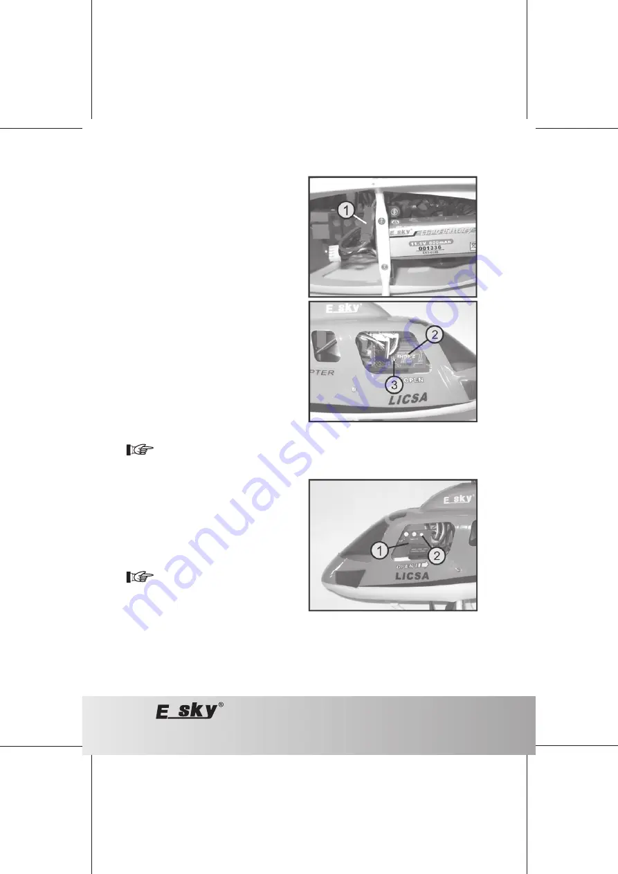
Figure 11
Figure 12
e) Connecting the Flight Battery
Slide the pitch function control lever (see figure 1, item 11)
and the trimming slider for the pitch function (see figure 1,
item 12) into their respective lowest position at the
transmitter.
Then switch on the transmitter and connect the flight battery
using the BEC connector (1), which is protected against
polarity reversal, to the receiver/controller component's
connection cable.
Looking through the open side window of the right of the
model, you can see the receiver component (2) with the
status LED (3).
If binding was set correctly, usually already in the factory,
the receiver's status LED flashes once and then lights up
permanently.
Secure radio transmission from transmitter to receiver is now
established and the two swash disc servos are running in
their basic positions.
If the status LED at the receiver only flashes once and then goes out, binding between transmitter and
receiver failed. The connection between transmitter and receiver must be disconnected and re-established.
For more information on binding transmitter and receiver, see the following chapter, section "Binding".
Looking through the open side window of the left of the
model, you can see the controller component (1) with the
status LED (2).
When the transmitter is set correctly, the status LED will
flash red 3 times and then green 2 times before it is
permanently lit and green.
Your model is now ready for operation and the electric motors
are cleared.
If the status LED at the controller component is
not green but red, the controller component has
not recognised the pitch control lever position
and the position of the respective trimming slider
as "motor out position".
In this case, the two swash plates will work, but
the drive motors do not start up.


