54
07/10
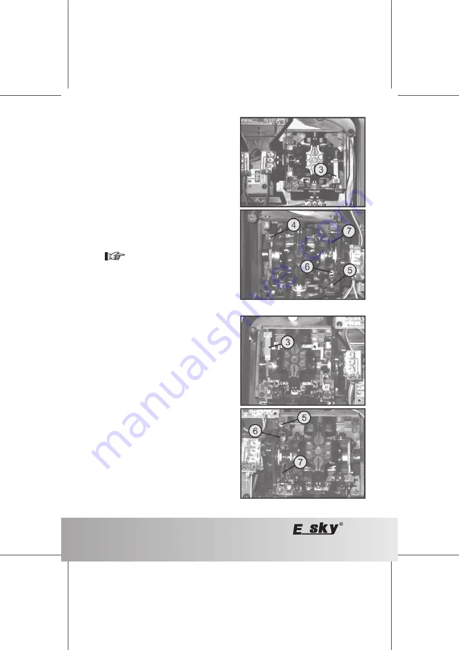
Figure 16
Figure 17
Mechanical conversion (only when switching the pitch
and nod functions)
Seen from the rear, loosen the stop spring (3) from the right
control lever aggregate and screw it on mirror-inverted to
the left control lever aggregate (seen from the rear) to the
attachment (4) (also see figure 17, top).
Loosen the adjuster screw (5) at the left control lever
aggregate (seen from the rear) for the restoring force of the
nod control stick so far that the traction spring (6) is as slack
as possible.
Now you can easily lift the screw together with the adjustment
mechanics upwards, disconnect the traction spring (4). Then
the complete setting mechanics can be easily lifted from
the guide.
Finally, lift out the return lever (7) together with the tension
spring (6).
Before you insert the release lever together with
the tension spring (seen from the rear) on the
right control stick aggregate, it makes sense to
fix the spring on the release lever with some in-
stant adhesive. This way, it remains at an exact
90° angle to the lever and only needs to be
inserted at the upper end.
Slide the return lever (7) below the horizontal shaft of the
right control stick lever with the glued-on spring (6) to the
front.
Then slide the screw (5) with the setting mechanics into the
prepared guide.
You best fix the tension spring in place with a thin wire or a
needle with a small catch on the tip.
When the spring was inserted, you can adjust the desired
control lever return force with the setting screw (5) and then
reattach the transmitter rear.
Finally, perform a function control of the entire system.


