60
07/10
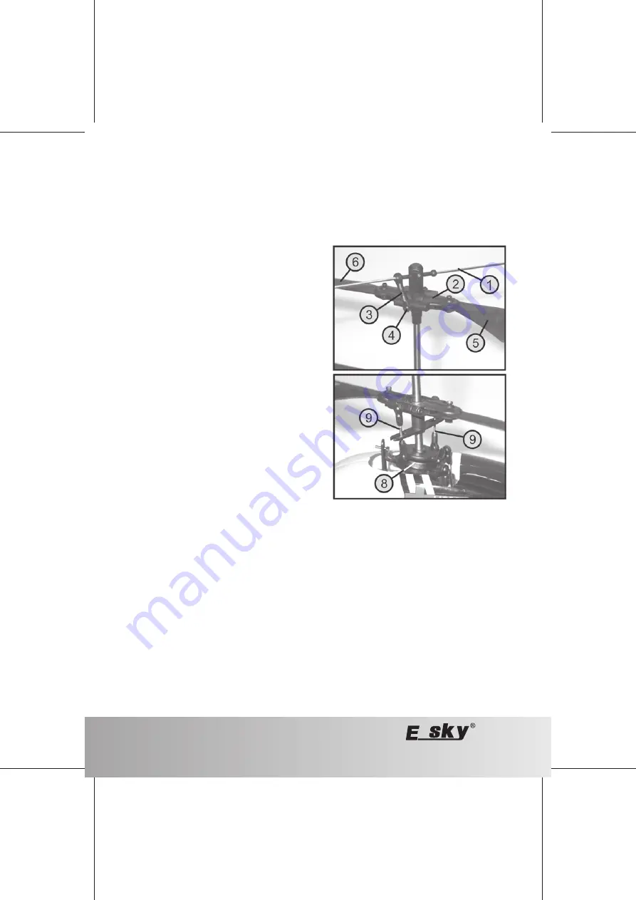
Figure 23
b) Setting the Track
For calm and stable hovering, the rotor blades of the upper and lower rotors must run cleanly on one level or in one
track.
Tracking is checked easiest if you attach a small piece of coloured adhesive take to one rotor blade tip.
Hovering on eye level, you will see at once if the two blades are on one track. If this is not the case, you can adjust
tracking on both rotor heads.
The upper rotor (figure 23, top) is stabilised using the
centrifugal weight(1). For this, the rotor hinge (2) is connected
to the centrifugal weight with a control rod (3).
After disconnecting the lower ball joint pan (4), you can twist
the pan to shorten or elongate the rod. Then connect the
ball joint pan again.
When the rod is shortened, the right rotor blade (5) will be a
little deeper and the left one (6) a little higher.
The lower rotor (figure 23, bottom) is controlled by the swash
plate (7) through two threaded rods (8).
Here, too, you can disconnect the ball joint pans and set the
length required by twisting them.
Important!
Only change the control rods in small steps of a half or whole turn of the joint pans. Then perform another
test flight to check if the change was sufficient.


