05/10
42
Flugvorbereitung
Flight preparation
Die RC-Anlage arbeitet einwandfrei, wenn das
Modell im Freifeld bei eingeschobener Anten-
ne aus ca. 25-30 m Entfernung noch korrekt
auf die Fernsteuerung anspricht. Achten Sie
bei diesem Test darauf, dass keine weiteren
Sender eingeschaltet sind. Unterbrechen Sie
den Test sofort, falls der Funkkontakt unterbro-
chen ist und die Empfangsanlage des Modells
unkontrollierte Steuerungen ausführt. Die RC-
Anlage arbeitet einwandfrei, wenn das Modell
aus ca. 30 m Entfernung noch korrekt auf die
Fernsteuersignale anspricht.
Fliegen Sie das Modell niemals mit fehlerhaft
arbeitender Fernsteuerung! Im günstigsten Fall
erleidet “nur” das Modell einen Schaden.
Funktionskontrolle des Flugreglers
Wenn Sie jetzt den linken Fernsteuerhebel vorwärts betäti-
gen, sollte der Elektromotor anlaufen und sich die Drehzahl
stufenlos regeln lassen.
Der Motor darf in der untersten Position (Neutralstellung) des
Gas/Pitchhebels noch nicht anlaufen!
Falls nötig, korrigieren Sie die Neutralstellung mit dem
Trimmhebel am Sender.
Bewegen Sie den Fernsteuerhebel nach vorwärts.
Die Drehgeschwindigkeit des Motors sollte kontinuierlich an-
steigen.
Einstellen der Helikopter-Elektronik
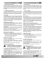
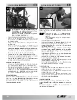
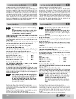
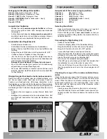
Auf dem Elektronik-Baustein (25) befinden sich zwei Einstellregler
(b, c), mit deren Hilfe Sie das Flug- und Steuerverhalten Ihres
Modellhelikopters bei Bedarf anpassen können.
ACHTUNG!
Trennen Sie den Flugakku vom Helikopter,
bevor Sie Änderungen vornehmen.
Der Regler ist ab Werk bereits voreingestellt, sodass Sie im
Regelfall keine Veränderungen vornehmen müssen. Sollten Sie
jedoch mit dem Flug- und Steuerverhalten Ihres Modellhelikopters
unzufrieden sein, können Sie folgende Änderungen vorneh-
men:
Kreiselwirkung
Neben den beiden elektronischen Drehzahlreglern für die
Elektromotoren ist noch ein Piezo-Kreiselsystem mit im
Elektronik-Baustein integriert. Dieses Kreisel-System sorgt
dafür, dass das Heck des Helikopters im Schwebeflug stabil
bleibt und nicht durch Luftzug oder Luftverwirbelungen ständig
zur Seite gedreht wird.
Das Kreisel-System kalibriert sich selbst, so-
bald der Flugakku angessteckt wird. Während
der Kalibrierung blinkt die LED. Bewegen Sie
den Heli nicht, bis der Vorgang beendet ist und
die LED dauerhaft leuchtet. Dies dauert einige
Sekunden.
Ansprechempfindlichkeit des Kreiselsystems
Die Ansprechempfindlichkeit (Gain) des Gyro kann mit dem
Einstellregler (b) eingestellt werden.
Je weiter Sie den Regler nach rechts drehen, um so stärker fal-
len die Korrekturen (Drehzahlunterscheide beider Rotoren) aus.
Das heisst, schon geringfügige Auslenkungen des Hecks führen
-
-
-
-
-
The RC system is working flawlessly if, in a free
field with the antenna pushed in, the model still
responds correctly to the remote control sys-
tem at a distance of approx 25-30 m. During this
test, be sure no other transmitters are switched
on. Abort the test immediately if the radio con-
tact is interrupted or the reception system for
the model executes piloting in an uncontrolled
manner. If the model responds correctly to the
remote control signals even from a distance of
approx. 30 m, the RC system is functioning cor-
rectly.
Never fly the model with a faulty remote control
system! Even in the most favourable situation,
at least the model will get damaged.
Functional check of the speed controller
Push the left remote control lever forward to start the electric
motor; the speed should be regulated continuously.
The motor should not start when the throttle lever is still
in the lowermost position (idle position)!
If required, rectify the idle position with the trimming lever on
the transmitter.
Move the remote control lever forward.
The rotating speed of the motor will increase continuously.
Adjusting the electronics
There are two adjusters (b, c) on the electronics module (25)
with which you can, if necessary, adjust the flying and steering
behaviour of your model helicopter.
ATTENTION!
Disconnect the flight battery from the helicopter
before making any changes.
The adjuster is pre-set ex factory, and in general, you should not
carry out any modification. However, if you are not satisfied with
the flying and steering behaviour of your model helicopter, you
can carry out the following modifications:
Gyroscopic action
Besides both electronic speed controllers for the electric driven
motors, there is also a Piezo gyroscope system integrated in
the electronics module. This gyroscope system helps the tail of
the helicopter to remain stable when hovering and prevents it
from swivelling to the side continuously due to air drafts or air
turbulences.
The gyro calibrates itself as soon as the flight
battery is inserted. The LED blinks during the
calibration. Do not move the helicopter till the
process ends and the LED gives out a steady
light. This lasts for a few seconds.
Responsiveness of the gyroscope system
The responsiveness (Gain) can be adjusted with the adjuster
(b).
The further you turn the adjuster to the right, the stronger the
corrections (speed differences of the two rotors).
This means that even slight deflections of the tail will cause the
electronics to steer in the opposite direction.
If the adjuster is turned too far towards the right, the helicopter
will tend to show oscillating movements around the yaw axis
(rotor shaft).
In this case, turn the adjuster a little bit towards the left again.
-
-
-
-
-


