background image

41

CHANGING 


OPTIC

 CARTRIDGE

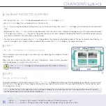
STEP 3

TURNING OFF THE DEVICE

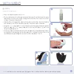
•  Turn off the device.

•  Unplug the mains lead of the device.

STEP 4

SÉPARATING THE MOBILE HEAD OF THE 

APPLICATOR USING THE 

EXTRACTOR

 AND 

EXTRACTING 

 CARTRIDGE IN PLACE 

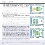
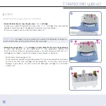
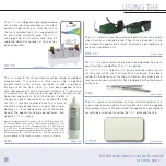
•  Hold the applicator so that 

 logo is facing 

you and the lead which connects the applicator 
to the base is on your left. Insert the 

Extractor


between  the  mobile  head  and  the  fixed  lateral 
casing of the applicator (photo 

23

).

•  Push the 

Extractor

 all the way inside the mobile 

head (photo 

24

).

•  Press simultaneously on the 2 locking tabs of the 

mobile head and remove the mobile head (photo 

25

).

•  Remove  the 

Extractor

  and  place  the  mobile 

head carefully on a flat surface (photo 

26

).

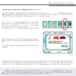
•  Identify the guiding notches on the 

optic

 cartridge 

(photo 

27

).

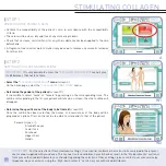
•  Carefully pull out the 

optic

 cartridge and remove 

it completely (photo 

28

).

23

24

25

26

27

28

Summary of Contents for WE-O

Page 1: ...User Manual...

Page 2: ...DARDS WARRANTY CONDITIONS CONTACT PACKAGE CONTENTS PRECAUTIONS FOR USE GLOSSARY INFORMATION PROVIDED BY TOUCH SCREEN USING REMOVING HAIR WITH STIMULATING COLLAGEN SYNTHESIS WITH REPLACING THE OPTIC CA...

Page 3: ...atest generation of pulsed light and offers complete safety of use in a compact format I have personally ensued that the utmost attention has been paid to the implementation of each you will appreciat...

Page 4: ...il of work and sharpener 1 gel flashing intended gel 1000 ml 1 Clean optical spray Only E Swin and authorised distributors are allowed to market and its accessories optic stop clean patches pen gel ma...

Page 5: ...ou must keep all the elements of the original packaging boxes padding etc The manufacturer s warranty for parts and labour will only be valid if the device is returned complete with all elements of it...

Page 6: ...rsed in water Never use if damaged never use in case of a functional anomaly appearing on the touch screen or after dropping non visible damage may be detrimental to your safety and to that of your pa...

Page 7: ...of the device When is running it must not come into contact with any of the items listed below in order to prevent any risk of injury obstruction or deterioration Clothing or any other object Hair Th...

Page 8: ...plied with On tattooed areas permanent make up for example lip tattoos or cosmetic tattoos of whatever colour In this case use the Stop delimitation plate supplied with your Persons suffering from ski...

Page 9: ...f any cosmetic residues from the skin After flash treatment the application of cosmetic products is possible y PRECAUTIONS REGARDING UV ARTIFICIAL UV ADMINISTERED IN BEAUTY SALONS Care must be taken w...

Page 10: ...level 1 which may be increased progressively depending upon skin tolerance In collagen stimulation mode Mark out the zone to receive flash treatment using the Pen Mask any beauty spots and other brown...

Page 11: ...tion occurs device may be used in complete safety Where is used in accordance with instructions secondary effects and complications are rare However all cosmetic treatments involve certain risks It is...

Page 12: ...12 GLOS y BASE Power cord connection Activation card slot Applicator holding area Visor to protect touchscreen Applicator cord support Ventilation grid Power cord connection...

Page 13: ...13 SARY y APPLICATOR Mobile head Release clips for mobile head Mobile head Applicator zone Applicator zone Air vents Trigger button Flash ready indicator Fixed side casing...

Page 14: ...s remaining represented by the symbol 8 Date and time 9 Return icon to previous menu This icon permits the modification of any selection entered previously 10 Icon not available on this device model 1...

Page 15: ...Pause icon to pause the flash treatment session Pressing this icon switches to pause mode The mode prohibits any flash emission by the applicator To exit pause mode simply press this icon again The C...

Page 16: ...CONFIGURATION menu screen E displays the sub menus see chapter on software options 21 PIN code 22 Language 23 Date and time 24 Maintenance 25 Volume and brightness 26 Cartridge contact E 21 23 25 22...

Page 17: ...17 17 BY TOUCH SCREEN...

Page 18: ......

Page 19: ......

Page 20: ...ttom left of the screen and below this the name of the device and its version number A personalized 4 digit PIN code may also be entered see chapter on software options in the present manual y IMPORTA...

Page 21: ...the activation card taking care not to damage it and re insert in its protective case Follow the procedure for turning off the device IMPORTANT Do not damage bend or cut the Optic cartridge activation...

Page 22: ...swin pro com go to Accessories and cartridges section then Mobile applicator head or from your authorised distributors VERIFICATION OF INTERNAL OPTICAL PARTS Before each use and before connecting your...

Page 23: ...applicator on a flat surface photo 6 Holding the mobile head the Filter will now be facing you photo 7 Apply the Clean spray beforehand to a lint free cloth photo 8 and clean the filter with the clot...

Page 24: ...THE PATIENT Patient has to be settled in an treatment chair lying or sitting Skin must be clean dry and free of any cosmetic products Make sure that no cream moisturizer oil or any other substance ha...

Page 25: ...depilated screen E2 Once the outline has been selected the names of 3 main areas of the body will be proposed as options Press on the main area which corresponds to that of the patient Female face tor...

Page 26: ...screen E4 These 6 icons represent the different types of skin colour from the lightest on the left to the darkest on the right Press on the colour which corresponds to the skin colour of the patient T...

Page 27: ...is screen permits the review of options selected by the user Validation is completed by pressing on the tick icon At any time it is possible to modify a setting by pressing on that setting or to retur...

Page 28: ...kin type n 5 is selected the following warning message will appear on the screen this message must be validated by pressing on OK Once all the settings have been validated the flash treatment session...

Page 29: ...ate to mask a substantial area which is not to receive flash treatment tattoos etc If flash treatment is to be applied to a large area do not spread gel over the entire area from the outset as it will...

Page 30: ...pplicator removed from the skin The applicator is then moved to the immediately adjacent area Take care to stretch the skin where it is at its thinnest in order to en sure that the glass element optic...

Page 31: ...in the applicator which will stop after a certain time the fans in the base will continue to run until the final disconnection of the mains lead of the device Using the Clean spray photo 13 clean the...

Page 32: ...ect male or female by pressing on the corresponding icons The outline corresponding to that of your patient will remain on screen the other outline will disappear Determine the specific area of the bo...

Page 33: ...power level must be selected according to the sensation reported by the client W3 x x W4 W2 bis IMPORTANT The default power level will be set at its base value This value permits the achievemet of hi...

Page 34: ...ng photosensitizing medications etc You are not using before the end of the necessary waiting period on skins which have recently been sunburnt You have read the instruction manual before proceeding w...

Page 35: ...to mask a substantial area which is not to receive flash treatment tattoos etc If flash treatment is to be applied to a large area do not spread gel over the entire area from the outset as it will dry...

Page 36: ...sential that the button should be held down and pressure applied to the mobile head throughout the duration of the flash The pressure must then be released and the applicator removed from the skin The...

Page 37: ...the optical guide photo 20 It is also possible to maintain the base in which the applicator is fitted by rinsing in water ensuring that it is dry again by the time the applicator is re fitted To do th...

Page 38: ......

Page 39: ......

Page 40: ...es decreases 3 by 3 y CHANGING THE OPTIC CARTRIDGE For the very first use is already equipped with an Optic cartridge Each Optic cartridge is associated with an activation card A device may be used by...

Page 41: ...e is on your left Insert the Extractor between the mobile head and the fixed lateral casing of the applicator photo 23 Push the Extractor all the way inside the mobile head photo 24 Press simultaneous...

Page 42: ...not the other way round Having fully engaged theopticcartridge you must check that it is correctly positioned It must be parallel to the fixed part of the applicator photo 30 If this is not the case...

Page 43: ...The filter is the flat element of red coloured glass see steps for the removal of internal optical parts 32 33 35 34 NOTE We recommend that the filter should be replaced whenever the optic cartridge...

Page 44: ...t hold the mobile head in place photo 36 pink arrows y STEP 8 INSERTING A NEW ACTIVATION CARD No code entry is required Remove the old activation card and insert the new card supplied with the Optic c...

Page 45: ...h credits during the operation of your device the warning screen screen H will appear In the event that there is no activation card or the activation card is damaged the warning screen screen I will a...

Page 46: ...be asked to insert your own PIN whenever is started To change the PIN code Access the CONFIGURATION menu Select the PIN code sub menu Using the digital keypad Enter the current PIN code and validate...

Page 47: ...ment is restricted to the after sales service SOUND AND LIGHT SETTING screen M You have the option to adjust the following Volume using the 2 arrows associated with the loudspeaker icon The brightness...

Page 48: ...ble obstruc tion of the low ventilation grid Do not cover the base of with a cloth so as not to block the ventilation located on the top part Do not touch the tube or the reflector with your fingers o...

Page 49: ...ttempt to touch the contact pads Do not attempt to dis mount the applicator other than for changing the cartridge Do not attempt to open device any in tervention must be carried out only by people dul...

Page 50: ...ng a damp towel or under the shower Remove gel from the optical parts of the mobile head of the applicator using a damp towel then apply the clean spray Ingredients quantity w v carbomer 0 5 2 TriEtan...

Page 51: ...of the optical parts or the replacement of the cartridge The fun stencils are used to mark out zones which are not to receive flash treatment allowing localized hair growth to be retained in fun shape...

Page 52: ...device must be cleaned with a clean cloth dampened with water without any additives TOUCHSCREEN The screen must be cleaned with a clean cloth that has been dampened with the spray Clean never spray Cl...

Page 53: ...nts likely to clog them Be careful not to drop liquid into the ventilation grid y STORAGE Place your in a room where the room temperature does not exceed 25 C for immediate use away from excessive hum...

Page 54: ...ic cartridge by carefully following the handling instructions SECU 02 No cartridge detected The device doesn t work Insert the optic cartridge by carefully following the handling ins tructions SECU 06...

Page 55: ......

Page 56: ...on against electric shock for parts that are applied onto the patient Part to be applied Type BF Electromedical device of Class II rating Device must be used indoors Keep the device dry Keep away from...

Page 57: ...re use E Swin SAS is affiliated to an eco organization which undertakes the collection and processing of end of life products y SPECIFICATIONS Technology IRPL Intense Regulated Pulsed Light Wavelengt...

Page 58: ...CISPR 11 Group 1 uses RF energy only for its internal function Therefore its radiated emissions are very low and are not likely to cause interference in nearby electronic equipement RF emissions CISP...

Page 59: ...ds Mains power quality should be that of a typical public low voltage power supply network If the user of requires continued operation during power mains inter ruption it is recommended that be powere...

Page 60: ...ON DISTANCES BETWEEN PORTABLE AND MOBILE RF COMMUNICATIONS EQUIP MENT AND is intended for use in an electromagnetic environment in which radiated RF disturbances are controlled The customer or user of...

Page 61: ...international organization It is consistent with the standard EN 60601 PRECAUTIONS FOR USE Never bring the base unit or the applicator into contact with water Do not open the base unit or the applica...

Page 62: ...d in this manual will invalidate the guarantee The company E Swin SAS shall not be held liable for any accident resulting from improper use or from failure to observe the present manual or the various...

Page 63: ...63 CONTACT commercial e swin com www e swin com FOR REQUESTS ABOUT AFTER SALES SERVICES OR SPARE PARTS CONTACT...

Page 64: ...www e swin com Ref M030GB000C13A...

Reviews: