background image

 - 5 -

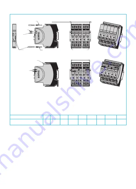
Mounting examples for ESX10-T

5 ESX10-TA

with busbars

5 ESX10-TB

with busbars

and jumpers

12.5 x n = width of protector block

e. g.  12.5 x 5 = 62.5

insert busbars

and protection slides

to be flush with housing sides

insert signal bars to 

be flush with housing 

and place them centrally 

over the contacts

LINE+ busbar

X22261102 grey

or X222611xx

0 V busbar

X22261102 grey

or X222611xx

signal bar

X22200503 grey

or X222005xx

or

jumper

X22200513 grey

remove protection 

against brush contact 

from bottom side

(12.5 x n)-3 = length of busbars ± 0.5

e. g.  (12.5 x 5)-3 = 59.5 ± 0.5 

insert protection 

against

brush contact

continuous busbar
500 mm length, cut

Mounting procedure: 
Before wiring insert busbars into protector block.
Max. 10 insertion/removal cycles for busbars.

Recommendation:
After 10 units the busbars and signal busbars should be interrupted and receive a new entry live

Table of lengths for busbars 
(X 222 611 02 / X 222 005 03 or cut off, see accessories)

No. of units

2

3

4

5

6

7

8

9

10

Length of busbar (mm) ± 0.5 mm

22

34.5

47

59.5

72

84.5

97

109.5

122

Summary of Contents for ESX10-TA-DC 24 V

Page 1: ...P 54 is achieved after installation in a UV protected fully enclosed room control cabinet IEC EN60079 0 and IEC EN 60079 14 have be observed for installation Safety This device is not protected agains...

Page 2: ...rcuit external free wheeling diode recommended with inductive load Several load outputs must not be connected in parallel Status output SF ESX10 T 114 124 127 Electrical data plus switching signal out...

Page 3: ...ESX10 TB 6 A l Electronic current limitation ILimit occurs at typically 1 8 x IN which means that under all overload conditions independent of the power supply and the resistance of the load circuit t...

Page 4: ...0 TB 124 Load Load Load 22 1 LINE RE SF 23 22 1 LINE RE SF 23 22 1 LINE RE SF 23 Reset button 3 0V 3 0V 3 0V 24 V 0 V 0 5 A ESX10 TA 100 1 LINE 1 LINE 1 LINE 1 LINE 2 LOAD 2 LOAD 2 LOAD 2 LOAD 3 0V 3...

Page 5: ...or jumper X22200513 grey remove protection against brush contact from bottom side 12 5 x n 3 length of busbars 0 5 e g 12 5 x 5 3 59 5 0 5 insert protection against brush contact continuous busbar 50...

Page 6: ...MENT ESX10 TA TB ISA 12 12 01 2015 UL File E320024 Operating Temperature Code T4 This equipment is suitable for use in Class Division 2 Groups A B C and D or non hazardous locations only T4 A 0 C to 5...

Page 7: ...7...

Page 8: ...nly In the interest of improved design performance and cost effectiveness the right to make changes in these specifications without notice is reserved Product markings may not be exactly as the orderi...

Reviews: