38
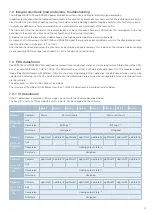
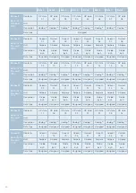
Byte 1
Byte 2
Byte 3
Byte 4
Byte 5
Byte 6
Byte 7
Byte 8
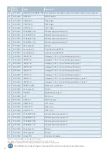
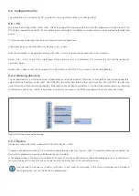
Frame 25
Basis-ID+31
Standard:
71Fh
Contents
LS state
09
LS state
10
LS state
11
LS state
12
LS state
13
LS state
14
SPARE
SPARE
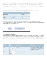
Unit
-
-
-
-
-
-
-
-
Conversion
Coding
(2)
Coding
(2)
Coding
(2)
Coding
(2)
Coding
(2)
Coding
(2)
-
-
Data type
Unsigned
Unsigned
Unsigned
Unsigned
Unsigned
Unsigned
-
-
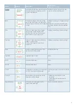
(1)
Coding of the I/O bit flags
0x0 OFF
0x1 ON
Most Significant Bit corresponds to input/output 64
Least Significant Bit corresponds to input/output 1
(2)
Coding of the output status
0 OFF
1 ON
2 INRUSH
3
Alarm threshold reached (ALARM)
100 Hardware trip (HARDTRIP)
101 Overload (HIGHTRIP)
102 Inrush trip (INRUSHTRIP)
103 Low current (LOWTRIP)
104 Undervoltage trip (PWRVTRIP)
105 Max. board temperature trip(BTTRIP)
200 Team trip (TEAMTRIP)
(3)
Coding of adjustment bit flag for current resolution
0
0.5 A
1
0.2 A (default)
If 0.5 A resolution was selected, the current values must be divided by 2 for conversion.
7.3.3 V3 datastream
The datastream format has been continuously developed over time to accommodate the higher number of outputs, soft inputs and
functions of the latest module generations.
If the V3 datastream is selected, CAN messages are sent with the structure described below.
The V3 datastream contains additional status frames that provide information about the device serial number and the firmware
version and are sent on request.
For CAN messages containing information on the load current and all other messages of the datastream, separate transmission
rates between 1 and 100 Hz can be set in the software.
The base ID is set to 0x700 by default, but this initial ID can be changed via the software.
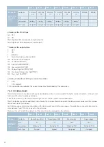
Byte 1
Byte 2
Byte 3
Byte 4
Byte 5
Byte 6
Byte 7
Byte 8
Frame 1
Basis-ID+0
Standard:
700h
Contents
Board temp. MAX
Board temp. MIN
Main supply
Logic supply
Unit
°C
°C
Volt
Volt
Conversion
Divide by 10
Divide by 10
Divide by 100
Divide by 100
Data type
Signed
Signed
Unsigned
Unsigned

