43
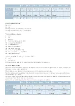
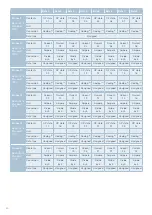
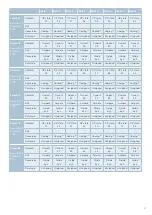
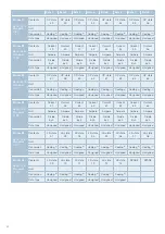
Byte 1
Byte 2
Byte 3
Byte 4
Byte 5
Byte 6
Byte 7
Byte 8
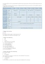
Frame 27
Basis-ID+48
Standard:
730 h
Contents
Module type
Main code branch
Main code version
Main code revision
Unit
-
-
-
-
Conversion
Coding
(4)
-
-
-
Data type
Unsigned
Unsigned
Unsigned
Unsigned
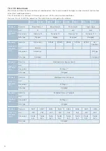
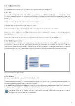
Frame 28
Basis-ID+49
Standard:
731h
Contents
Serial number
SPARE
SPARE
SPARE
SPARE
Unit
-
-
-
-
-
Conversion
-
-
-
-
-
Data type
Unsigned
-
-
-
-
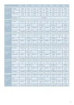
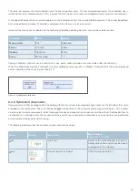
Frame 29
Basis-ID+50
Standard:
732h
Contents
File name (configuration file played on module)
Unit
-
Conversion
-
Data type
Last 8 ASCII characters of the file name
(1)
Coding of the I/O bit flags
0x0 OFF
0x1 ON
Most Significant Bit corresponds to input/output 64 or 128
Least Significant Bit corresponds to input/output 1 or 65
(2)
Coding of the output status
0 OFF
1 ON
2 INRUSH
3
Alarm threshold reached (ALARM)
100 Hardware trip (HARDTRIP)
101 Overload (HIGHTRIP)
102 Inrush trip (INRUSHTRIP)
103 Low current (LOWTRIP)
104 Undervoltage trip (PWRVTRIP)
105 Max. board temperature trip(BTTRIP)
200 Team trip (TEAMTRIP)
(3)
Overview and coding of the settings flags
Bit 0: Current resolution
0
0.5 A
1
0.2 A (default)
If 0.5 A resolution was selected, the current values must be divided by 2 for conversion.
Bit 1: Analogue value resolution
0
0. V/Bit (default)
1
0.02 V/Bit
If 0.02 A resolution was selected, the current values must be divided by 50 for conversion.
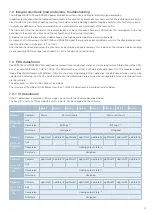
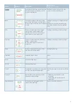
The following three CAN frames provide information about the serial number and the software version of the module and are sent
on request.
The conditions for sending the CAN messages can be defined via the PDUsetup software. To do this, use the EVENT IN schematic
symbol (selection of CAN_VER_TX).


