background image

45

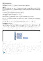
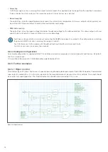
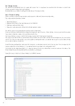
Figure 11: PDUsetup configuration interface

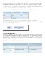
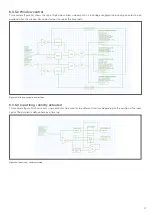
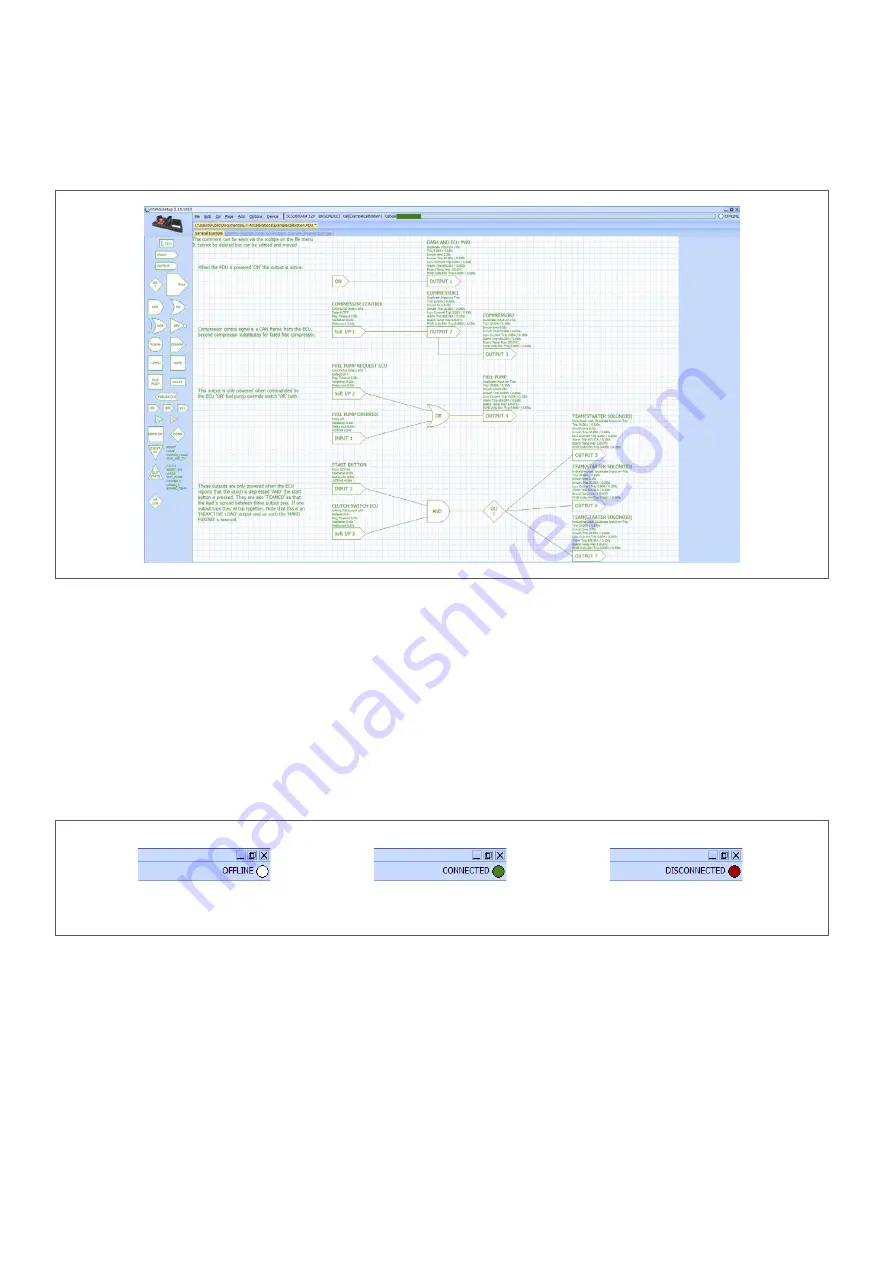
Figure 12: Display connection status

8  PDUsetup configuration software

The PDUsetup configuration software is used to create SCS1000 and SCS3000 configurations to control the behaviour of the 
modules. This is done with the help of a graphically displayed logic control.
Figure 11 shows the general structure of the configuration interface, which is described in more detail in the following chapters.

8.1  User interface

8.1.1  Menu bar

All menu buttons and menu sub-items can be accessed via keyboard shortcuts. Each option has an underlined letter marking its 
keyboard shortcut or the shortcut is displayed to the left of the drop-down menu. 

The menu bar displays calibration information, such as the device being configured, the programme name and the size of the 
programme. On the far right of the menu bar, the connection status of a connected device is displayed.

No device connected 

Successfully connected 

Connection lost

Summary of Contents for SCS1000

Page 1: ...Operation manual SCS Smart Control Systems SCS1000 3000 Configuration environment PDUsetup...

Page 2: ...SCS3000 48 13 4 2 4 Pin assignment SCS3000 34 13 4 2 5 Pin assignment SCS3000 48 17 4 2 6 Dimensions of the SCS3000 64 21 4 2 7 Pin assignment SCS3000 64 21 4 3 Load outputs Current limitation inrush...

Page 3: ...nents 49 8 3 3 I O properties 53 8 3 3 1 Input properties 53 8 3 3 2 Output properties 54 8 3 4 Example configuration 56 8 3 5 Further examples 56 8 3 5 1 Wiper control 56 8 3 5 2 Window control 57 8...

Page 4: ...shipment 2 2 Qualified personnel This user manual must exclusively be used by qualified personnel who are able on their training and experience to realise arising problems when handling the product a...

Page 5: ...on Besides power distribution the SCS1000 and SCS3000 provide more transparency on the load side by feeding back the current and condition values Additional safety is guaranteed by the integral electr...

Page 6: ...r large centralised system architectures Performance and logic combined in one module Series SCS3000 16 SCS1000 16HS AL SCS1000 16LS AL Load outputs 16 16 16 Low Side Total current 200 A 160 A 160 A M...

Page 7: ...16HS AL The following table shows the pin assignment of the SCS1000 16 high side version Ampacity of outputs 4 x 35 A high side PWM 125 Hz 2 x 35 A high side 10 x 12 A high side Figure 3 Dimensions o...

Page 8: ...3 k activatable pull up to 5 V 23 24 16AWG INPUT 05 Analogue 0 32V 24 24 16AWG INPUT 06 Analogue 0 32V 25 24 16AWG INPUT 07 Analogue 0 32V 26 24 16AWG INPUT 08 Analogue 0 32V 27 24 16AWG INPUT 09 Anal...

Page 9: ...OUTPUT 15 Low side 12 A 16 24 16AWG OUTPUT 16 Low side 12 A 17 24 16AWG CAN 01 CAN low 18 24 16AWG CAN 01 CAN high 19 24 16AWG INPUT 01 Analogue 0 32 V 3 k activatable pull up to 5 V 20 24 16AWG INPU...

Page 10: ...es are suitable for a centralised system deployment and replace different individual modules with only one device which combines logic and power distribution The SCS3000 modules have up to 5 H bridges...

Page 11: ...le pull up to 5 V 6 24 16AWG INPUT 08 Analogue 0 32 V 3 k activatable pull up to 5 V 7 24 16AWG INPUT 07 Analogue 0 32 V 3 k activatable pull up to 5 V 8 24 16AWG INPUT 06 Analogue 0 32 V 3 k activata...

Page 12: ...output 01 Low side low side PWM 41 24 16AWG WARNING AND RESET SW Error output for LED against ground for manual reset connect to ground 42 24 16AWG Output 16D High side with diode 43 24 16AWG Output...

Page 13: ...the main connection and load outputs 4 2 3 Dimensions of the SCS3000 34 and SCS3000 48 Figure 5 Dimensions of the SCS3000 34 and SCS3000 48 4 2 4 Pin assignment SCS3000 34 The following table shows t...

Page 14: ...art 1 2 16 20 12AWG Output 6 High side low side low side PWM half bridge full bridge soft start 1 2 17 20 12AWG Output 5 High side low side low side PWM half bridge full bridge soft start 1 2 18 20 12...

Page 15: ...ted 32 n c Not connected 33 n c Not connected 34 n c Not connected 35 n c Not connected 36 n c Not connected 37 n c Not connected 38 n c Not connected 39 24 16AWG Output 33 High side 12 A 40 24 16AWG...

Page 16: ...RNET2 RX Ethernet communication port 1 66 24 16AWG ETHERNET1 TX Ethernet communication port 1 67 24 16AWG Power ground Battery 68 24 16AWG Low output 13 Low side low side PWM 69 24 16AWG Low output 14...

Page 17: ...ows the SCS3000 48 pin assignment Ampacity of outputs 10 x 40 A high side low side 5 H bridges PWM 20 kHz 10 x 35 A high side 28 x 12 A high side Supply pin Mating plug Surlok SLPPC BSR0 size 50 200 A...

Page 18: ...e low side low side PWM half bridge full bridge soft start 1 2 Plug 2 Mating plug TE 1703998 1 cap 1703997 1 Pin Cross section Name Description 1 n c Not connected 2 n c Not connected 3 n c Not connec...

Page 19: ...7 24 16AWG INPUT 01 Analogue 0 32 V 3 k activatable pull up to 5 V 48 24 16AWG INPUT 03 Analogue 0 32 V 3 k activatable pull up to 5 V 49 24 16AWG INPUT 05 Analogue 0 32 V 3 k activatable pull up to 5...

Page 20: ...alogue 0 32 V 3 k activatable pull up to 5 V wake 3 77 24 16AWG INPUT 16 Analogue 0 32 V 3 k activatable pull up to 5 V wake 3 78 24 16AWG SENSOR GND Sensor mass protected 79 24 16AWG Power ground Bat...

Page 21: ...00 350 A Pin Cross section Name Description 1 Supply Battery Plug 1 Mating plug TE 1 1534127 1 cap 9 1394050 1 Pin Cross section Name Description 1 20 12AWG Power ground Battery 2 20 12AWG Output 20 H...

Page 22: ...art 1 2 20 20 12AWG Output 2 High side low side low side PWM half bridge full bridge soft start 1 2 21 20 12AWG Output 1 High side low side low side PWM half bridge full bridge soft start 1 2 Plug 2 M...

Page 23: ...4 16AWG Output 29 High side 12 A 42 24 16AWG Output 27 High side 12 A 43 24 16AWG Output 25 High side 12 A 44 24 16AWG Output 23 High side 12 A 45 24 16AWG Output 21 High side 12 A 46 24 16AWG Low out...

Page 24: ...l up to 5 V 75 24 16AWG INPUT 12 Analogue 0 32 V 3 k activatable pull up to 5 V 76 24 16AWG INPUT 14 Analogue 0 32 V 3 k activatable pull up to 5 V wake 3 77 24 16AWG INPUT 16 Analogue 0 32 V 3 k acti...

Page 25: ...of 0 32 VDC The measured value resolution is determined on 0 2 V by default To achieve higher accuracy a resolution of 0 02 V can also be selected With this setting however only voltage values up to...

Page 26: ...6 1 Environmental tests and approvals The following approval test was carried out for all SCS1000 versions The following approval test was carried out for all SCS3000 versions The following tests were...

Page 27: ...O 16750 4 5 6 2 3 Composite temp and humidity ISO 16750 4 5 6 2 4 Dewing ISO 16750 4 5 7 Steady state damp heat ISO 16750 5 4 Chemical loads EN 60529 IP6x EN 60529 IPx7 ISO 13766 1 ISO 14982 EN 13309...

Page 28: ...apter 6 2 1 shows an example of a derating curve of the SCS3000 64 module 6 2 1 SCS3000 64 Fig 7 shows the derating of the maximum total current of the SCS3000 64 over the ambient temperature Cable cr...

Page 29: ...t can be configured via the PDUsetup software A direct connection of CAN keypads is also possible via the configuration software 7 1 Connection and CAN standard The SCS1000 and SCS3000 support the CAN...

Page 30: ...display a negative value data can be marked as signed This changes the way data bits are translated into decimal numbers By reversing the sign on the value of the last digit as in figure 10 a byte co...

Page 31: ...otection can be set for each channel via PDUsetup This also applies to the trip behaviour in the event of an inrush and the configuration of the warning thresholds A tripping in case of too low curren...

Page 32: ...7 Standard 707h Contents current17 current18 current19 current20 current21 current22 current23 current24 Unit Ampere Ampere Ampere Ampere Ampere Ampere Ampere Ampere Conversion Divide by 5 Divide by...

Page 33: ...Unit Ampere Ampere Ampere Ampere Conversion Coding 2 Divide by 5 Coding 2 Divide by 5 Coding 2 Divide by 5 Coding 2 Divide by 5 Data type Unsigned Unsigned Unsigned Unsigned Unsigned Unsigned Unsigne...

Page 34: ...gned Unsigned Unsigned Frame 2 Basis ID 1 Standard 701h Contents Total current SPARE SPARE SPARE SPARE SPARE Set ting flags Unit Ampere Conversion Divide by 5 Bit flags 3 Data type Unsigned Unsigned F...

Page 35: ...Data type Unsigned Unsigned Unsigned Unsigned Unsigned Unsigned Unsigned Unsigned Frame 10 Basis ID 14 Standard 70Eh Contents OP state 09 Current 09 OP state 10 Current 10 OP state 11 Current 11 OP st...

Page 36: ...by 5 Coding 2 Divide by 5 Coding 2 Divide by 5 Data type Unsigned Unsigned Unsigned Unsigned Unsigned Unsigned Unsigned Unsigned Frame 16 Basis ID 20 Standard 714h Contents OP state 33 Current 33 OP...

Page 37: ...5 Coding 2 Divide by 5 Coding 2 Divide by 5 Coding 2 Divide by 5 Data type Unsigned Unsigned Unsigned Unsigned Unsigned Unsigned Unsigned Unsigned Frame 22 Basis ID 26 Standard 71Ah Contents OP state...

Page 38: ...selected the current values must be divided by 2 for conversion 7 3 3 V3 datastream The datastream format has been continuously developed over time to accommodate the higher number of outputs soft in...

Page 39: ...ontents Validated status soft inputs 65 128 Unit Conversion Bit flags 1 Data type Unsigned Frame 6 Basis ID 6 Standard 706h Contents Validated status soft outputs Unit Conversion Bit flags 1 Data type...

Page 40: ...nsigned Unsigned Unsigned Unsigned Unsigned Unsigned Unsigned Frame 12 Basis ID 15 Standard 70Fh Contents Current 09 Current 10 Current 11 Current 12 Current 13 Current 14 Current 15 Current 16 Unit A...

Page 41: ...2 Coding 2 Data type Unsigned Unsigned Unsigned Unsigned Unsigned Unsigned Unsigned Unsigned Frame 18 Basis ID 21 Standard 715h Contents Current 33 Current 34 Current 35 Current 36 Current 37 Current...

Page 42: ...Coding 2 Coding 2 Coding 2 Coding 2 Coding 2 Coding 2 Coding 2 Coding 2 Data type Unsigned Unsigned Unsigned Unsigned Unsigned Unsigned Unsigned Unsigned Frame 24 Basis ID 27 Standard 71Bh Contents Cu...

Page 43: ...the output status 0 OFF 1 ON 2 INRUSH 3 Alarm threshold reached ALARM 100 Hardware trip HARDTRIP 101 Overload HIGHTRIP 102 Inrush trip INRUSHTRIP 103 Low current LOWTRIP 104 Undervoltage trip PWRVTRI...

Page 44: ...logue value is evaluated A negative value means no change Analogue values received via soft inputs can be further processed within the software and used for calculations If a soft input is directly co...

Page 45: ...e which is described in more detail in the following chapters 8 1 User interface 8 1 1 Menu bar All menu buttons and menu sub items can be accessed via keyboard shortcuts Each option has an underlined...

Page 46: ...em Page The PDUsetup can be used to create configurations for more than one device at a time A unique name is assigned to the respective module The individual devices are displayed in tabs directly be...

Page 47: ...applications and can be edited in PDUsetup To change the current working directory select Working Directory under File Use CREATE to create a new folder in the current location Use SELECT to select th...

Page 48: ...ly The configuration selection must match the actual operating voltage 24 V calibrations result in lower maximum currents Change Identity An identity is a security feature that restricts access to dev...

Page 49: ...ause is given figure 17 8 3 2 Symbols Components Components can either be dragged onto the display with the mouse from the component panel shown on the left side of the screen or added via the Add men...

Page 50: ...iple PWM components can be linked together to get more duty cycle options If a soft input controls the PWM symbol the duty cycle can be flexibly set via the value of the soft input 1 100 corresponds t...

Page 51: ...h until reset R sets output low Adding or removing set and reset input Flip Flop Output D data input only with rising edge at C clock input S sets output high until reset R sets output low Adding or r...

Page 52: ...of a hysteresis Maths operation Performs the selected mathematical operation with the applied values A and B and makes the analogue value available at the output Selection of the mathematical operati...

Page 53: ...state when no input signal is present Alarm on timeout Default on timeout only for soft inputs Selection between triggering an alarm or switching to the default state when the timeout of the CAN mess...

Page 54: ...t properties Figure 21 Output properties Validation Requires an input signal to be consistent for the defined period of time before it is acknowledged as input The validation causes a small delay but...

Page 55: ...set alarm time the status output goes high regardless of the trip condition Trip The output triggers an error if the set trip current is exceeded for longer than the set time period This switches off...

Page 56: ...SET device event in symbol in the configuration or switching the physical RESET pin or by switching the supply on and off Any CAN frame sent to the module with the defined fault reset identifier will...

Page 57: ...load when the window hits an obstacle or the top of the travel path 8 3 5 3 Input long shortly actuated This example figure 24 shows how a single output can be used for two different functions dependi...

Page 58: ...his example figure 26 shows how to connect a Grayhill keypad with a LED key colour that changes depending on the initial state 8 3 6 Communication settings Settings for bus communication can be made u...

Page 59: ...lues up to 5 V can be displayed Soft I P base preV2 9 Start address of the soft I Os only for PDU firmware before V2 9 Datastream base ID Start address of the CAN datastream containing output states a...

Page 60: ...ive connection with a module for example in Monitor mode is not possible during this time The Power Config is saved as a text file that can be saved on the PC and loaded into devices The Save and Load...

Page 61: ...must be assigned before simulation output nodes can be left free The simulation includes the state of all internal components so that each step and state can be monitored Switch the simulation mode on...

Page 62: ...the ability to select multiple com ponents with the mouse Enable Disable auto offline If the auto offline function is enabled PDUsetup returns to offline mode if the connection to a device has been i...

Page 63: ...9 List of abbreviations AWG American Wire Gauge CAN Controller Area Network ECU Electronic Controller Unit HSD High Side Driver ID Identificator IP International Protection ISO International Organiza...

Page 64: ...iestra e 2 8 90518 ALTDORF GERMANY Phone 49 9187 10 0 Fax 49 9187 10 397 E mail info e t a de www e t a de Bedienungsanleitung Instruction manual BA_SCS1000 3000_ENG_250121 Index Ausgabe Issue 01 2021...

Reviews: