46
8.1.2 Symbols
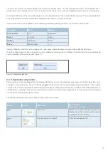
The component bar on the left side of the interface shows all available schematic diagram symbols. These can be grabbed and
dragged into the schematic diagram area with the mouse, or inserted via the »Add« menu.
8.1.3 Schematic diagram
The calibration schematic diagram can be divided into several pages to improve visibility. Each page can be given a name that
appears in the tabs above the schematic diagram area. These tabs can be used to switch between pages. This is also possible
via numerical links under the menu item »Page«.
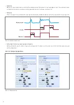
The PDUsetup can be used to create configurations for more than one device at a time. A unique name is assigned to the respective
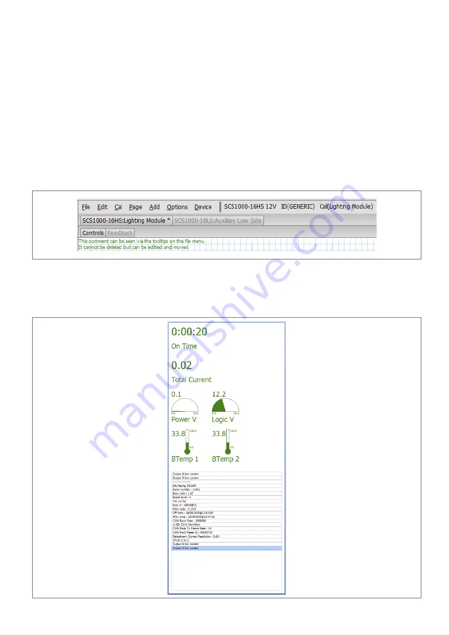
module. The individual devices are displayed in tabs directly below the menu bar (figure 13). These tabs can be used to switch
between the modules and to display the respective schematic diagram pages. The selection of the respective device is also possible
via numerical links under the menu item »Cal«.
8.1.4 Device information
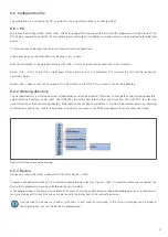
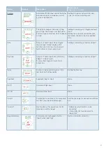
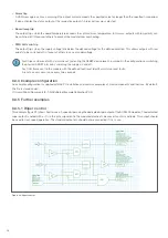
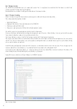
Once a module is connected, device information is displayed on the right side of the screen. This includes the total current
consumption, device temperature, voltage, »On time« and all other device messages (figure 14).
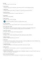
Figure 13: Multiunit configuration
Figure 14: Device information


