49
The menu bar displays the total calibration size and the connection status. The bar displayed represents the calibration size in
relation to the total available memory. If this is above the limit, the bar turns yellow and programming of a device is not allowed.
In the upper left corner of the schematic diagram is a short information text, the so-called tooltip comment. This cannot be deleted,
but can be edited and moved. The tooltip is displayed in the file menu as a file comment.
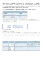
Instead of the mouse, the keyboard with the following alternative operating elements can also be used for control:
Common Windows shortcuts can be used to cut, copy, paste, undo and redo or are accessible under the edit menu.
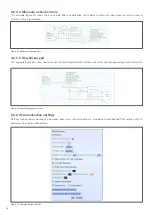
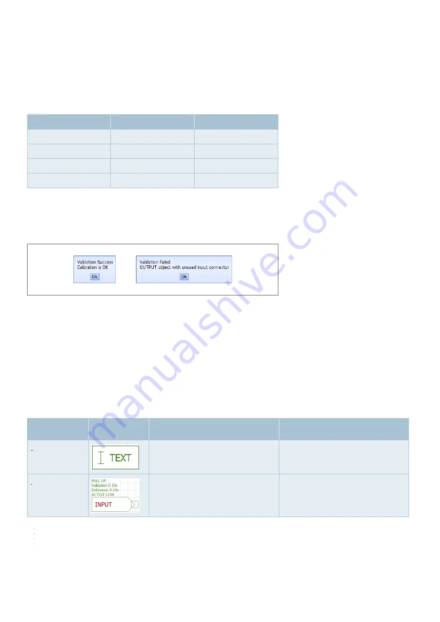
When the configuration creation is complete, it can be validated by selecting »Cal«, »Validate«. If validation fails, the error is displayed
and an indication of the cause is given (figure 17).
8.3.2 Symbols/Components
Components can either be dragged onto the display with the mouse from the component panel shown on the left side of the screen
or added via the »Add« menu. They can then be dragged into position on the schematic diagram grid. Hold down <Ctrl> or draw
a box to select multiple components. Select component nodes and drag to draw connections between them. Add connections to
create bends by selecting part of the connection or the end of a loose connection. Components and connections can be deleted
or more options displayed by right-clicking.
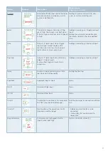
The following table describes the available symbols and how they work.
Figure 17: Configuration validation
Command
Mouse
Keypad
Move pointer
Pull
Arrow keys
Select
Left-click
Space
Options
Right-click
Enter
Zoom
Mouse wheel
+/-
Name
Symbol
Description
Menu options
(Right click on symbol)
Text
Insert text
Edit or fix text. When the text is fixed, it is
displayed in yellow and cannot be moved
or edited until it is unlocked.
Input
Physical input or soft input
Other features (see 8.3.3.1)

