55
• Output#
Assignment of a physical high side output, a physical low side output or a soft output (CAN). CAN outputs are set up under
»Cal«, »Communications«.
• Name
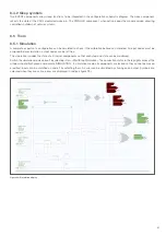
Enter a name that is displayed in the schematic diagram display.
• PWM
Definition of a physical output as a PWM output. The analogue value present at the symbol input is used to set the duty cycle.
The positive analogue value corresponds to the duty cycle in percent.
The PWM frequency is set by default to the maximum possible frequency of the output (20 kHz or 125 Hz, see SCS1000 and
SCS3000 data sheet).
• Inductive load
Determine if an inductive load is controlled at the output (motors, pumps, loads containing coils). Setting an output as inductive
increases the required circuit protection and leads to an adjustment of the soft start behaviour.
• Low side pull up (only for low side outputs)
Activation of the low side pull-up to 5 V. This is intended for PWM logic where an input requires a full signal.
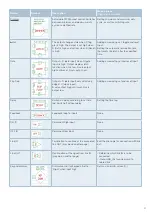
• Status output
Selection of the status output behavior.
Copy input while tripped – When an error occurs, the status output goes high when the output is on and stays low when the
output is off.
Trip active – When an error occurs, the status output goes high regardless of the switching state of the output.
Alarm active – When the current exceeds the alarm value for the set alarm time, the status output goes high regardless of the
trip condition.
• Trip
The output triggers an error if the set trip current is exceeded for longer than the set time period. This switches off the faulty output.
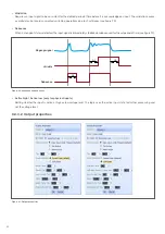
• Inrush handling
Selection between inrush fuse and soft start for outputs with soft start capability.
When an output is initially switched on, it often draws a higher inrush current for a certain time. This duration is called the inrush
time. During this time, it may be desirable to define a higher trip value to prevent too early tripping.
Alternatively, soft start-capable outputs can actively limit the current consumption during the defined soft start period.
• Inrush time
Definition of the inrush phase duration. This determines how long the higher inrush tripping is active.
• Inrush trip
During the inrush phase (inrush time), the set higher trip current applies instead of the standard trip current.
The output triggers an error if the set trip current is exceeded for longer than the set time period. This switches off the faulty
output.
• Soft start time
Definition of the soft start phase duration.
• Soft start current/ramp time
Definition of the maximum current to which the system should limit. It must be higher than the normal current consumption
during operation. The ramp time indicates the minimum time that must elapse before the output may be fully switched on.
• Low current trip
The output triggers an error if the current is below the specified current for longer than the specified time.

