background image

ET DC BLUE ADVANCED INSTALLER 2012.025.12.05.2014 


18 

www.et.co.za 


SELECTING A LOCK MODE. 


Default – Off 


NB!! The “E-Coms” output on the control card is designated to be used with an “E-Coms” Relay module, 

when using any electric lock. These modules are only available via ET Systems. 


For further instructions on the E-Coms relay module, consult the instructions included with it.  


For assistance the product support department can be contacted on: 

0861 109 9238 or 

support@et.co.za


In strike lock mode, the lock relay will energise 0.5sec before the motor begins opening and release 

again 0.5sec after the motor has begun moving. (Total 1sec. pulse length) 


In magnetic lock mode, the lock relay will energise, 0.5sec before the motor starts opening and 5 seconds 

later, the lock relay module switches off again. (Total 5sec. pulse length) 


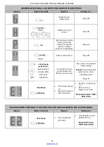
From Standby  Mode 


Action 

Response 

To enter the Program 

menu. Press and hold 

SET button until buzzer 

beeps twice. 


Display begins flashing 

“P” and buzzer beeps 

twice to confirm the 

main program menu is 

active. 


Select lock setup by 

scrolling up with the UP 

button until “

” flashes. 


Display flashes “

” to 

confirm lock setup 

mode is selected. 


Press and release SET 

button to enter lock 

setup. 


Buzzer beeps once and 

current lock status is 

displayed.   


Press and release the UP 

or DOWN buttons to 

scroll to the desired 

setting.    


0 = Off.       

1 = Strike lock.   

2 = Magnetic  lock.   


Press and release the SET 

button to save the new 

setting to memory and 

exit back to the main 

program menu.   


The buzzer beeps once 

and the display returns 

to flashing “P”. 


To 

Scroll up or down 

to next program 

option. 

OR 

Press and release EXIT to 

return to Standby mode. 

Summary of Contents for DC BLUE ADVANCED

Page 1: ...ET DC BLUE ADVANCED INSTALLER 2012 025 12 05 2014 1 www et co za Domestic garage door operator Installer Instructions ...

Page 2: ...ring and setup 12 Wiring of optional extra devices to the system 13 Control panel dashboard and programming menu summary How to navigate the menu 14 Programming Open and closed limit setup and door load profiling 15 Programming Setting the obstruction force sensing safety level 16 Programming Activating safety beam mode 17 Programming Activating and selecting the auto close time 18 Programming Sel...

Page 3: ... positioninits travel the door should neither rise nor fall If the door does rise or fall re balance the tensioning system Tensioning should only be carriedout by a qualifiedand experiencedperson o The door material must be sound and whole Ensure the areas where the operator attaches have been re enforced The door hardware must be in good serviceable condition o Ensure the wall above the door is s...

Page 4: ...e door may not be operatedout of clear sight o Ensures that childrenare kept clear of the door area and that childrendo not play withthe remote transmitters o Is instructednot to attempt to repair or adjust the automationsystemand to be aware of the danger of continuing to use the automationsystemin an unsafe conditionbefore a service providerattends to it o Is proficient intesting the unit s safe...

Page 5: ... screws M6 x 20mm 4 27 Motor head 1 9 Emergency release cord1 1m with warning tag 1 28 Control panel dashboard 1 10 Emergency release cordplastic knob handle 1 29 Courtesy light diffuser lens 1 11 Pivot pins 8mm x 25mm 2 30 Drawbar 1 12 Hanging strap drawbar attachment bracket 1 31 Drawbar spring dampener and shock absorber 1 13 Drawbar brackets 3 32 Batteryconnectionbeneathdust cover sticker 1 14...

Page 6: ...ledge traveller Ensure the 4 machine screws are securely fastened Do this prior to installing the drawbar CAUTION TO DISENGAGE AND MOVE DOOR MANUALLY Warning Door may plummet closed when released W hile pulling t he emergency release cord dow nw ard move t he door open or closed by hand TO RE ENGAGEAND LOCK DOOR BACK ONTO DRIVE Let t he cord go and move door open or closed unt il the sledge t rave...

Page 7: ...cket in the case of a standard single track or double track overhead sectional garage door system NB The wall mount bracket is one of the components that take the majority of the load in a garage door automation system Extra care needs to be taken to ensure the bracket is securely fastened and that whatever the bracket is fastened to can withstand force equal to the force of the door when the spri...

Page 8: ... a garage door automation system Extra care needs to be taken to ensure that the bracket is securely fastened Whatever the bracket is fastened to must also withstand a force equal to the force of the door when the spring balancing of the door is removed For example if a balancing spring snaps INSTALLING THE LINK ARM See page 5 for component identification Close the door fully Install the curved li...

Page 9: ...the wall mount bracket at this height where it is positioned above the centre of the door as shown in the diagram below NB The wall mount bracket is one of the components that will take the majority of the load in a garage door automation system Extra care needs to be taken to ensure that the bracket is securely fastened Whatever the bracket is fastened to must also withstand a force equal to the ...

Page 10: ...e cotter pins Raise the drawbar up and out of the way of the door Install the link arm into both the sledge traveller and door mount bracket using the 25mm pivot pins and remaining two cotter pins Prepare and install the hanging straps so that when the door is in the full open position the link arm lays 180 to the door Do not use the curved link arm extension in this type of installation The diagr...

Page 11: ...4 of the M6 Nylock nuts fasten the battery atop the drawbar as shown below Remove the sticker covering the battery plug socket on the motor head and insert the battery lead plug The battery plug is moulded in such a way as to only be inserted in one direction Ensure the plug is in firmly SUPPLYING HOUSEHOLD POWER TO THE MOTOR HEAD The DC BLUE ADVANCED comes supplied with an IEC and SANS compliant ...

Page 12: ...ET DC BLUE ADVANCED INSTALLER 2012 025 12 05 2014 12 www et co za OPTIONAL EXTRA DEVICES WIRING CONNECTIONS ...

Page 13: ... the SET button until the buzzer beeps twice Once in the Programming menu use the up and down buttons to scroll between options For further instruction on changing settings refer to the instruction tables on the page indicated for each option EXIT BUTTON To exit a setup option without changing the current setting for that option press and release the EXIT button The menu will exit back one level N...

Page 14: ...firm the door direction while fine tuning or When satisfied the door is in the correct open position press the SET button to advance to the close limit setup The buzzer beeps once and the C symbol displays to indicate the closed limit position must be set Press and hold the DOWN button to lower the door to the required closed position The u symbol displays as the door closes Fine tune using the UP...

Page 15: ...EL Default level 3 From Standby Mode Action Response To enter the Program menu Press and hold SET button until buzzer beeps twice Display begins flashing P and buzzer beeps twice to confirm the main program menu is active Scroll up with the UP button until F flashes Display flashes F to confirm safety force setup mode is selected Press and release SET button to enter safety force setup Buzzer beep...

Page 16: ...ins flashing P and buzzer beeps twice to confirm the main program menu is active Select safety beams setup by scrolling up with the UP button until b flashes Display flashes b to confirm safety beam setup mode is selected Press and release SET button to enter safety beam setup Buzzer beeps once and current beam status is displayed 0 Off and 1 On Press and release the UP button for On or DOWN butto...

Page 17: ...shing P and buzzer beeps twice to confirm the main program menu is active Select auto close setup by scrolling up with the UP button until A flashes Display flashes A to confirm auto close setup mode is selected Press and release SET button to enter auto close setup Buzzer beeps once and current auto close status is displayed Press and release the UP or DOWN buttons to scroll to the desired settin...

Page 18: ...motor starts opening and 5 seconds later the lock relay module switches off again Total 5sec pulse length From Standby Mode Action Response To enter the Program menu Press and hold SET button until buzzer beeps twice Display begins flashing P and buzzer beeps twice to confirm the main program menu is active Select lock setup by scrolling up with the UP button until flashes Display flashes to confi...

Page 19: ...r receiver programming Buzzer beeps once and b for BT is displayed Press and release the UP or DOWN buttons to scroll to the channel the remote button must be learnt into b BT button trigger channel L LT Courtesy light trigger channel or Press and hold desired remote button LED on remote transmitter illuminates While still holding the desired remote button press and release the SET button 1 on dis...

Page 20: ...p by scrolling up with the UP button until r flashes Display flashes r to confirm receiver setup mode is selected Press and release SET button to enter receiver setup Buzzer beeps once and b is displayed Press and release the UP or DOWN buttons to scroll to the C option C is displayed Press and hold desired remote button to be erased LED on remote transmitter illuminates While still holding the de...

Page 21: ...ll to the E option E is displayed Press and hold SET button and do not release While still holding the SET button Press and release UP button to start master erase Release both buttons once beeps begin Display flashes E and buzzer beeps intermittently to warn that master erase is about to begin NB Pressing and holding EXIT at this point will abort the master erase Master erase routine is running W...

Page 22: ...and display shows b Buzzer beeps once and display shows b Press and hold required remote button LED on remote transmitter remains lit Press and release the SET button 1 on display and 1 beep user code successfully registered 2 on display and 2 beeps user code already in the receiver memory 3 on display and 3 beeps Unsuccessful because no code was seen within 4 sec of the SET button being pressed M...

Page 23: ... hardwired trigger Door begins opening and courtesy light switches on Wait for door to reach the full open position Door stops and waits in the open position Courtesy light remains on for a further 3 minutes Press and release either the remote button trigger or the hardwired trigger Door begins closing and if the courtesy light had previously timed out and switched off it will switch on again for ...

Page 24: ...and release either the remote button trigger or the hardwired trigger before the door reaches the full open position Door stops and waits for next instruction Courtesy light remains on for a further 3 minutes Press and release either the remote button trigger or the hardwired trigger Door begins closing and if the courtesy light had previously timed out and switched off it will switch on again for...

Page 25: ...s on Stop door while opening or simply wait until it reaches the open position Door stops and waits at the required open position Courtesy light remains on for a further 3 minutes Press and hold the remote button trigger 10 seconds until buzzer beeps Buzzer beeps rapidly to indicate party mode is active TO CONFIRM Any attempt to operate the door normally Buzzer repeats rapid beeps to indicate the ...

Page 26: ...s on Whilst buzzer is still sounding Press and release the remote trigger button to activate Holiday lock out Buzzer beeps light flashes rapidly and display shows H to indicate Holiday lock out is active TO CONFIRM Any attempt to operate the door normally Buzzer beeps light flashes rapidly and display shows H to indicate Holiday lock out is active TO DE ACTIVATE Press and hold remote courtesy ligh...

Page 27: ...osed position Courtesy light off Lock relay module off Press and release either the remote button trigger or the hardwired trigger 0 5 seconds before the door begins opening the lock relay module and courtesy light switches on Door begins opening lock relay module and courtesy light remains on 0 5 seconds after door begins opening the lock relay module switches off again Door continues opening and...

Page 28: ...closed position Courtesy light and lock relay module off Press and release either the remote button trigger or the hardwired trigger 0 5 seconds before the door begins opening the lock relay module and courtesy light switches on Door begins opening lock relay module and courtesy light remains on 5 seconds after door begins opening the lock relay module switches off again Door continues opening and...

Page 29: ...and buzzer flashes and sounds three times before door begins closing automatically ADVANCED FEATURES Safety beam input NB This input only affects the closing cycle Action Response Door closing Light on Interrupt the safety beams Display shows b door stops and begins opening once again Light remains on Safety beam still interrupted Door reaches full open position Display continues to show b as long...

Page 30: ...ter any BT transaction when the household mains power is off Action Response Every operation of the door from any position Light will come on for 3 minutes and door operates If the light is off and the L courtesy light button on the remote is pressed and released Light will come on for 60 minutes If the light is on and the L courtesy light button on the remote is pressed and released The courtesy ...

Page 31: ...On battery power only Re connect household mains supply To test Check that light switches on when operating door Page 30 Door stops Motor fuse blown or Encoder faulty or disconnected Replace motor fuse or Reconnect or replace encoder Press and release EXIT when done WARNINGS WHEN ATTEMPTING TO PROGRAM THE OPEN AND CLOSED LIMITS AND DOOR PROFILING Display Buzzer and door Reason Resolve by Door stop...

Page 32: ... accompanied by the original invoice All claims made by the end user must be directedto their respective service provider installer The following conditions will disqualifythis product fromthe warranty as laid out above These conditions are non negotiable Any unauthorized non manufacturer modifications to the product or components thereof The use of the ET DC BLUE ADVANCED operator inheavy traffic...

Reviews: