16
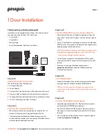
Installing the limit actuator.
1/2
1/2
M
ag
net
M
ag
net
Reed swit
ch
This diagram depicts how to install the limit actuator.
1.
Push the gate up against the closed stopper.
2. Remove the rack screw (Holding the nylon teeth to the steel angle) closest to being
in line with the limit switch. Or in the case of steel rack, weld a M4 x 20 machine bolt
upside down on top of the spine of the rack in line with the limit switch.
3. Fasten the actuator down onto the rack using either the M4 x 20 self-tapping screw
supplied with the kit or with a nut in the case of steel rack.
4. Adjust the actuator so that it is approximately halfway across the limit switch.
5. Move the gate open and then closed again. Ensure the limit LED comes on before the
gate impacts with the closed stopper. (Positive closed mode will always close the gate
the last 50mm if selected in programming)
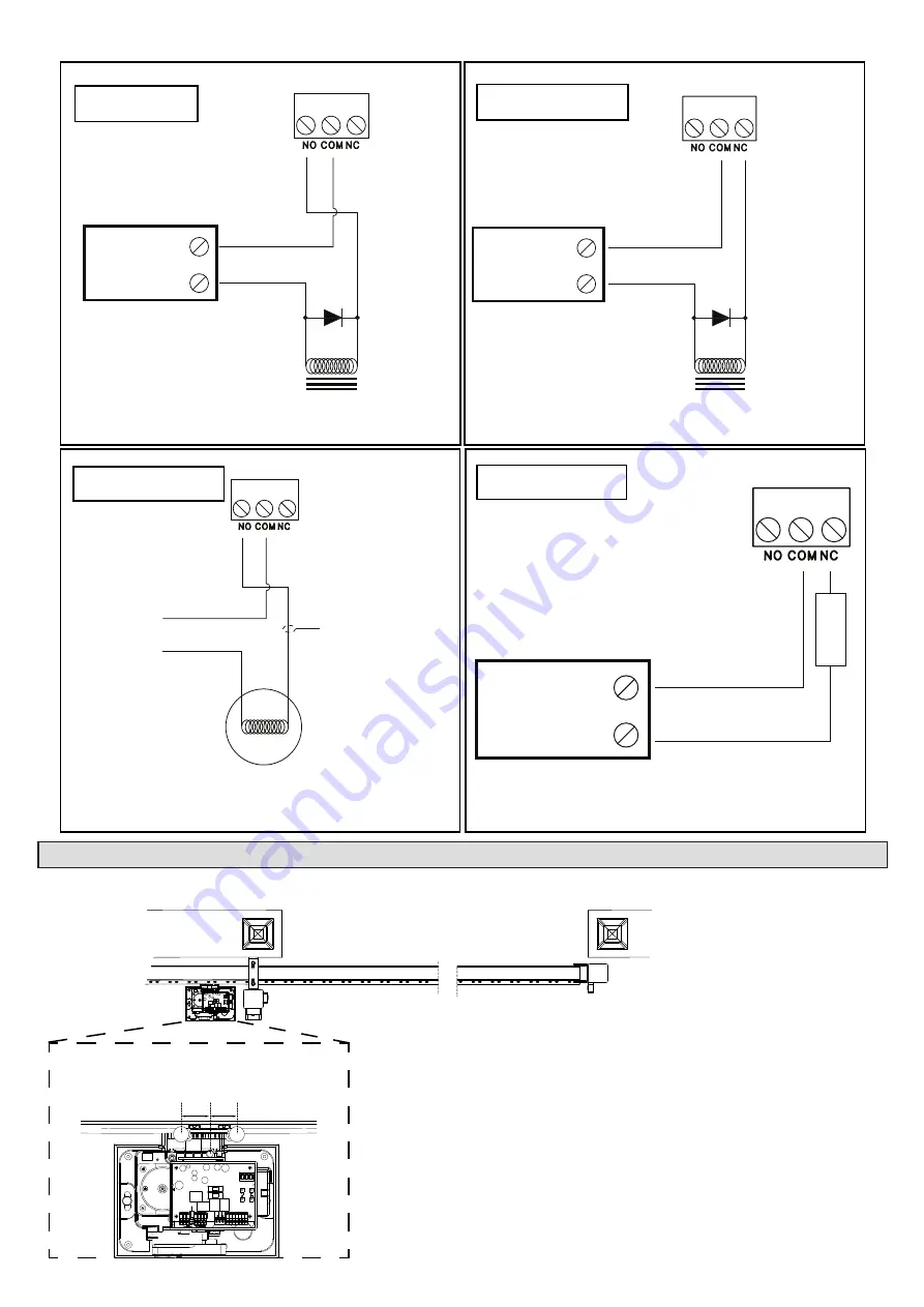
Wiring and termination of the control card - Auxiliary relay examples.
AUX Relay
Battery back-up
power-supply rated
to match the lock
load.
+
0V
+
0V
IN4007 back
EMF diode.
Strike lock.
AUX Relay
Battery back-up
power-supply rated
to match the lock
load.
+
0V
+
0V
IN4007 back
EMF diode.
Magnetic lock.
AUX Relay
220V non-inductive
light bulb/s.
3A continuous.
5A peak.
Live
Neutral
Minimum 1,5mm
cross section wire.
AUX Relay
Alarm panel zone
24hr zone
0V
E.
O
.L
Strike Lock Example
Magnetic Lock Example
Courtesy light Example
Alarm zone Example


