background image


FILE: IP 100 Service manual.doc                                               2004.05.01


E-TECH Co., Ltd                                                                                                                                16/19


            4) IF Circuit 

         The first signals from Q102 are fed to the matched pair crystal filter FL101, then IF signals are amplified 

  in Q103.    And those signals are fed to U101 which is composed of the second local oscillator, second 

  local oscillator, second mixer, limiter amplifier, quadrature detector and active filter circuit. The second 

  local oscillator at 20.945MHz with X 101 and is fed to the second mixer with the first IF signals to   

convert into 455kHz second IF signals.     

5)  Audio and squelch Circuit 

      The detected audio signals are put through a 6dB/oct de-emphasis circuit made up of Q602. 

  The signal is then applied to audio power amplifier U603 to obtain enough power to driver the speaker. 

  Part of the recovered noise signal is fed to the integrated operational amplifier inside U101 which   

makes up an low pass filter.    The sensitivity of squelch is adjusted by VR 101. 

   5-3 VCO Circuit 

       The transmit / receive frequency is directly generated by the Colpitts oscillation circuit contains Q402,   

Q405. 


Summary of Contents for IP-100

Page 1: ... IP 100 service manual doc 2004 05 01 E TECH Co Ltd 1 19 Table of Contents 1 Introduction 2 Description of Unit 3 Technical Specifications 4 Theory of Operation 5 Circuit Descriptions 6 Alignment Procedure ...

Page 2: ......

Page 3: ......

Page 4: ...n receiver and a direct FM transmitter modulator A special integrated circuit provides support to sub audible signaling CTCSS DCS and most of the receiving parts are switched off periodically in the power save mode to reduce battery current drain during standby 2 Description of Unit Items Model Radio IP 100 Antenna IA 156 1700mAh Li Ion battery pack BL 1800 Desktop rapid charter IC 170 Adaptor Sup...

Page 5: ... 2A When Receiving 0 5W 300mA Transmit standby 60mA Receiver standby PSC MODE 50mA 9 Microphone Internal Condenser Microphone External Speaker Micro phone is available 10 Operating temperature range 30 60 11 Size 56 W x100 H x34 D 12 Weight 285g 3 2 Transmitter 1 Power Output HIGH 5W LOW 1W 2 Modulation 8K5F3E 16K0F3E 3 Oscillator method PLL 4 Frequency Stability less than 0 00025 2 5PPM 5 Maximum...

Page 6: ...annel Selectivity 60 dB Narrow 70 dB Wide 6 Distortion 5 1 kHz 60 7 Hum Noise 40 dB HP8920A 300Hz 3kHz BPF 8 Audio output 1000 mW 9 BAND SPREAD 38MHz 10 Speaker size 45 pi 4 Theory of Operation EXTERNAL VIEW 12 Antenn 4 Emergency Key 9 PTT button 10 Mic 2 Monitor Button 14 LCD 1 TX POWER HIGH LOW 3 Scan button 8 Squelch 6 Menu Button 11 POWER ON OFF Volume control 13 Ear Mic Jack PC Programming Ja...

Page 7: ...s tone is adjustable 13 Rx Tone select In the menu rx dcs ctcss tone is adjustable 14 Group Defines group tone You can select tone code for group and it is used as a default value 0 9 and a b c d available And A is used as a basic value 15 BEEP ON OFF BEEP sound ON OFF 16 KEY LOCK LOCK UNLOCK Button KEY 17 SQUELCH Squelch level is adjustable 18 AUTO SQUELCH Squelch level is adjustable automaticall...

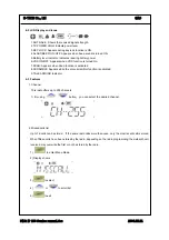
Page 8: ...when Scan function is activated 8 SCRAMBLE Appears while the voice scrambler function is activated 9 TALK AROUND Indicator 4 3 Features 1 Channel This radio offers up to 255 channels 1 By using button you can select the desired channel 2 Missed calls list Up to 16 calls can be stored If the same radio calls more than once only the most recent call is stored When fifteen calls have been stored by t...

Page 9: ... until 3 to select 4 or to scroll list 5 to exit 4 Status call list 4 1 Making STATUS call 1 to enter Menu Mode 2 or to until 3 to select 4 or to scroll list 5 Push PTT KEY for sending message on the LCD 4 2 Make STATUS Message 1 to enter Menu Mode 2 or to until 3 to select 4 or to scroll list 5 to SELECT ...

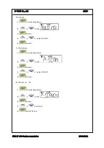
Page 10: ...ect 4 or to select ON OFF 6 Tx power 1 to enter Menu Mode 2 or to until 3 to select 4 or to select HIGH LOW POWER 5 to select 7 Tx Tone Selecting Transmitting TONE CTCSS DCS 1 to enter Menu Mode 2 or to until 3 to select 4 or to Select TONE을 either CTCSS or DCS 0 NON TONE 1 38 CTCSS 101 183 DCS TONE 5 to select exit ...

Page 11: ... to until 3 to select 4 or to select TONE either CTCSS or DCS 0 NON TONE 1 38 CTCSS 101 183 DCS TONE 5 to select exit 9 Group Changing GROUP Tone 1 to enter Menu Mode 2 or to until 3 to select 4 or to select scroll list 5 to select exit 10 Beep on off 1 to enter Menu Mode 2 or to until 3 to select 4 or to select on off 5 to select ...

Page 12: ...lect key lock unlock 5 to select 12 Squelch level 16 level is available 0 terminate sq function 1 to enter Menu Mode 2 or to until 3 to select 4 or to the scroll list 5 to select exit 13 Auto Squelch 1 to enter Menu Mode 2 or to until 3 to select 4 or to select on off 5 to select 14 Scan 1 to enter Menu Mode 2 or to until 3 to scan ...

Page 13: ...o enter Menu Mode 2 or to until 3 to select 4 or to select ON OFF 5 to select 16 Vox on off 1 to enter Menu Mode 2 or to until 3 to select 4 or to select ON OFF 5 to select 17 Vox Level 16 level is available 1 to enter Menu Mode 2 or to until 3 to select 4 or to scroll list 5 to select for exit ...

Page 14: ...enter Menu Mode 2 or to until 3 to select 4 or to select ON OFF 5 to select 19 Priority Scan 1 to enter Menu Mode 2 or to until 3 to select 4 or to select ON OFF 5 to select 20 Priority scan CH 1 to enter Menu Mode 2 or to until 3 to select 4 or to scroll list 5 to select for exit ...

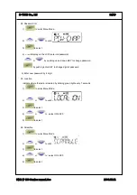
Page 15: ...save 1 to enter Menu Mode 2 or to until 3 to select 4 or to select ON OFF 5 to select 22 Talkaround 1 to enter Menu Mode 2 or to until 3 to select 4 or to select ON OFF 5 to select 23 Password 1 to enter Menu Mode 2 or to until 3 to select 4 or to select ON OFF 5 to select ...

Page 16: ...ing up and down KEY to change password by pushing enter KEY to change digit of password 5 Enter new password by 4 digit 25 Location Indicate where the radio is located by blinking green light every 7 seconds 1 to enter Menu Mode 2 or to until 3 to select 4 or to select ON OFF 5 to select 26 Scramble 1 to enter Menu Mode 2 or to until 3 to select 4 or to select ON OFF 5 to select ...

Page 17: ...upplied through antenna switch Q203 Q204 to a low pass filter made up and then applied to Antenna Jack 5 2 Receiver 1 LOWPASS FILTER and Antenna switching circuit Signals from antenna connector fed to the antenna switching circuit through the low pass filter consisting of L212 214 In receiving mode D204 D202 is turned off isolates the antenna from the transmitter circuit and matching circuitry so ...

Page 18: ... 101 and is fed to the second mixer with the first IF signals to convert into 455kHz second IF signals 5 Audio and squelch Circuit The detected audio signals are put through a 6dB oct de emphasis circuit made up of Q602 The signal is then applied to audio power amplifier U603 to obtain enough power to driver the speaker Part of the recovered noise signal is fed to the integrated operational amplif...

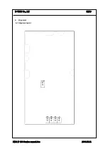
Page 19: ...FILE IP 100 Service manual doc 2004 05 01 E TECH Co Ltd 17 19 6 Alignment 6 1 Alignment point ...

Page 20: ...using VR 302 at the level of 0 45 kHz 0 k05 zH 6 4 Receiver Set up Receiving Mode at SSG 60d Bm At the frequency range of 146 025 MHz FM 1 5 kHz adjust Volume at 0 5 W Sensitivity at the level of 12 dB SINAD check whether it is under 119 dBm and SQ LEVEL8 is between 117 dBm 123 dBm by using VR101 In case of out of range adjust it at 120 dBm 6 5 Wideband specification check At the frequency range o...

Reviews: