FRONT SUSPENSION AND STEERING
E
Read all of Section Band this section before attempting any procedure. Pay particular attention to all Notes, Cautions and Warnings
FRONT SUSPENSION
I
NOTE
I
In the following text, there are references to
removing/installing bolts etc. Additional hard
ware (nuts, washers etc.) that are removed must always be
installed in their original positions unless otherwise specified.
Non-specified torque specifications are as shown in the table
contained in Section A.
A
WARNING.A.
To
reduce the possibility
of personal injury, follow
the lifting procedure in
Section B of this manual. Place wheel chocks in front
and behind the rear wheels. Check the stability of the
vehicle on the jack stands before starting any repair
procedure. Never work on a vehicle that is supported
by a jack alone.
Front Shock Absorber Replacement
Tool List
Qty. Required
Wrench, 9/16" ............................................................. 1
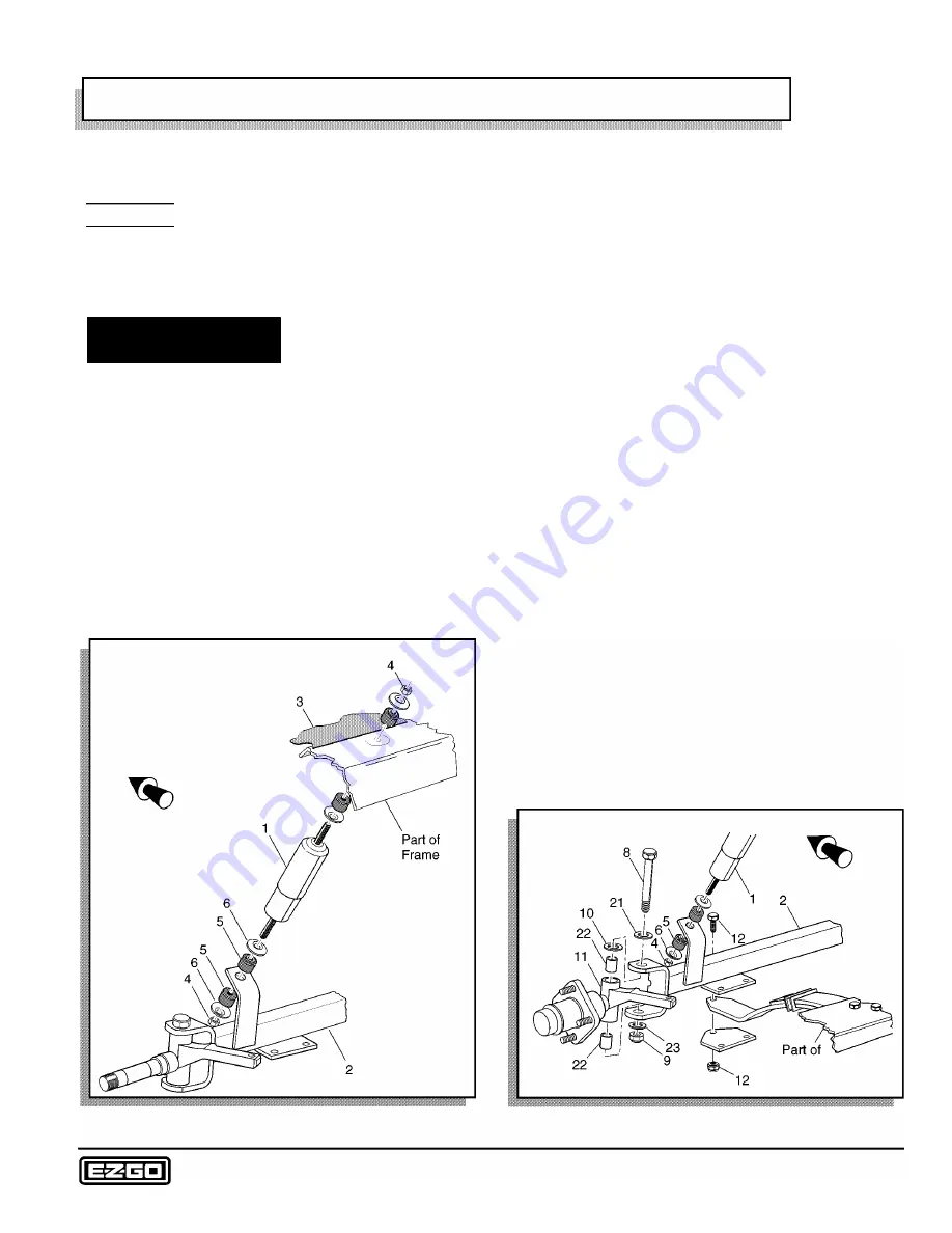
Remove the nut (4) from the bottom of the shock
absorber (1) at the front axle (2) (Ref Fig. 1 on page E-1 ).
Compress the shock absorber to clear the mounting
bracket.
Front of Vehicle
Fig. 1 Shock Absorber Replacement
On metal body vehicles, bend the tabs that secure the
flexible grass shield (3) to the cowl down and pull the
grass shield down to provide access to the top of the
shock absorber.
Loosen the nut (4) securing the top of the shock absorber
to the vehicle frame and then rotate the shock absorber
while holding the nut in place with a wrench.
Repeat the process on the lower shock absorber nut (4).
Remove the shock absorber.
The installation of the shock absorber is the reverse of
disassembly, except that the mounting nuts should be
tightened until the rubber bushings (5) expand to the
diameter of the shock absorber washers (6).
Front Axle Replacement
Tool List
Qty. Required
Wheel chocks .............................................................. 4
Floor jack ..................................................................... 1
Jack stands ................................................................. 2
Impact wrench, 1 /2" drive ............................................ 1
Impact socket, 3/4", 1/2" drive ..................................... 1
Pliers ........................................................................... 1
Wrench, 3/4" ................................................................ 1
Plastic faced hammer .................................................. 1
Socket, 9/16", 1 /2" drive .............................................. 1
Wrench, 9/16" .............................................................. 1
Torque wrench, 1 /2" drive, ft. lbs . ................................ 1
Lift and support front of vehicle. (See SAFETY section.)
Remove the front wheels. Remove the bottom shock
absorber mounting hardware (Ref Fig. 2 on page E-1 ).
Front of Vehicle
Frame
Fig. 2 Front Axle Replacement
Repair and Service Manual
Page E-1
Summary of Contents for 4 CADDY 1999
Page 6: ...TABLE OF CONTENTS Notes __________________________ _ Page iv Repair and Service Manual...
Page 10: ...SAFETY INFORMATION Notes _________________________ _ Page viii Repair and Service Manual...
Page 26: ...SAFETY Notes _ _ ___________________________ _ Page B ii Repair and Service Manual...
Page 48: ...BODY Notes _ _ ___________________________ _ Page C ii Repair and Service Manual...
Page 56: ...WHEELS AND TIRES Notes __________________________ _ Page D ii Repair and Service Manual...
Page 72: ...SPEED CONTROL Notes _ _ ________________________ _ Page F ii Repair and Service Manual...
Page 80: ...ENGINE Notes _ _ __________________________ _ Page G ii Repair and Service Manual...
Page 94: ...FUEL SYSTEM Notes _ _ _________________________ _ Page H ii Repair and Service Manual...
Page 110: ...ELECTRICAL Notes _ _ _________________________ _ Page K ii Repair and Service Manual...
Page 120: ...ACCESSORY WIRING Notes __________________________ _ Page L ii Repair and Service Manual...
Page 148: ...REAR SUSPENSION Notes __________________________ _ Page N ii Repair and Service Manual...
Page 154: ...REAR AXLE Notes _ _ ___________________________ _ Page P ii Repair and Service Manual...
Page 158: ...PAINT Notes _ _ ___________________________ _ Page Q ii Repair and Service Manual...
Page 162: ...TROUBLESHOOTING Notes _ _ ________________________ _ Page R ii Repair and Service Manual...
Page 170: ...LIMITED WARRANTY Notes __________________________ _ Page S ii Repair and Service Manual...
Page 176: ...LIMITED WARRANTY Notes __________________________ _ Page S 6 Repair and Service Manual...
Page 178: ...GENERAL SPECIFICATIONS Notes _________________________ _ Page T ii Repair and Service Manual...


