ENGINE
Read all of Section B and this section before attempting any procedure. Pay particular attention to all Notes, Cautions and Warnings
/
Adjust with screwdriver
®
Screw type
adjuster
Cam lobe up
�
_ Release by
G)
turning wrench
1
Cam lobe down
Hold screwdriver
VALVE OPEN
©
.004 (.10 mm)
1----'--�---1
1-�....>.......C'-
Valve clearance
measured here
---{:====::::::l�- with the engine
VALVE CLOSED
cold
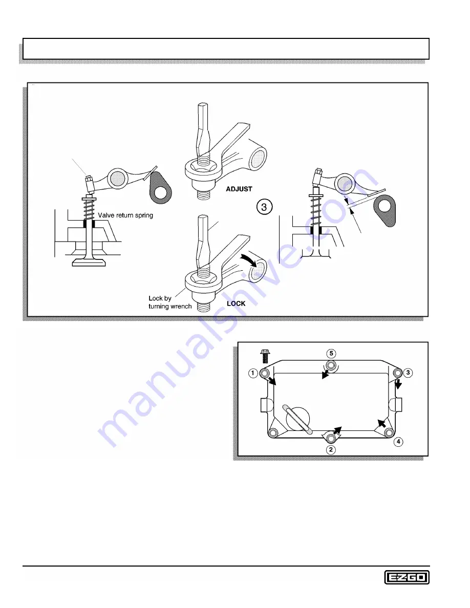
Fig. 3 Overhead Valve Adjustment
between the valve rocker and the heel (lowest portion) of
the cam. If the gauge slides in and out with some light
drag felt, the valve does not require any adjustment.
If the gauge is hard to insert or withdraw, the valve is too
tight. Similarly if the gauge slides in and out with no resis
tance, the valve is too loose. To correct either of these
undesirable conditions, loosen the jam nut of the adjuster
and loosen or tighten the adjuster using a snug fitting
straight blade screwdriver. Slide the feeler gauge back
and forth between the rocker and cam until light resis
tance is felt. Hold the adjuster with the screwdriver and
tighten the jam nut with a box wrench. Confirm the
adjustment using the feeler gauge and readjust as nec
essary.
Manually rotate the engine until the cam lobe for the next
valve is in the fully down position and check/adjust the
valve as previously described. Repeat the process with
the remaining two valves.
Valve Cover Installation
Tool List
Qty. Required
Socket, 10 mm, 3/8" drive ........................................... 1
®
Fig. 4 Valve Cover Tightening Sequence
Torque wrench, 3/8" drive (in. lbs.) .............................. 1
It is important to use proper tightening procedures when
replacing the valve cover, since distortion of the valve
cover may result in oil leakage (Ref Fig. 4 on page G-4).
Examine the 'O' ring gasket for nicks, tears or other dam
age and replace if any damage is found. Wipe the valve
cover and gasket clean, paying special attention to the
inner groove surface. Position the gasket in the groove in
Page G-4
Repair and Service Manual
Summary of Contents for 4 CADDY 1999
Page 6: ...TABLE OF CONTENTS Notes __________________________ _ Page iv Repair and Service Manual...
Page 10: ...SAFETY INFORMATION Notes _________________________ _ Page viii Repair and Service Manual...
Page 26: ...SAFETY Notes _ _ ___________________________ _ Page B ii Repair and Service Manual...
Page 48: ...BODY Notes _ _ ___________________________ _ Page C ii Repair and Service Manual...
Page 56: ...WHEELS AND TIRES Notes __________________________ _ Page D ii Repair and Service Manual...
Page 72: ...SPEED CONTROL Notes _ _ ________________________ _ Page F ii Repair and Service Manual...
Page 80: ...ENGINE Notes _ _ __________________________ _ Page G ii Repair and Service Manual...
Page 94: ...FUEL SYSTEM Notes _ _ _________________________ _ Page H ii Repair and Service Manual...
Page 110: ...ELECTRICAL Notes _ _ _________________________ _ Page K ii Repair and Service Manual...
Page 120: ...ACCESSORY WIRING Notes __________________________ _ Page L ii Repair and Service Manual...
Page 148: ...REAR SUSPENSION Notes __________________________ _ Page N ii Repair and Service Manual...
Page 154: ...REAR AXLE Notes _ _ ___________________________ _ Page P ii Repair and Service Manual...
Page 158: ...PAINT Notes _ _ ___________________________ _ Page Q ii Repair and Service Manual...
Page 162: ...TROUBLESHOOTING Notes _ _ ________________________ _ Page R ii Repair and Service Manual...
Page 170: ...LIMITED WARRANTY Notes __________________________ _ Page S ii Repair and Service Manual...
Page 176: ...LIMITED WARRANTY Notes __________________________ _ Page S 6 Repair and Service Manual...
Page 178: ...GENERAL SPECIFICATIONS Notes _________________________ _ Page T ii Repair and Service Manual...


