ENGINE
Read all of Section Band this section before attempting any procedure. Pay particular attention to all Notes, Cautions and Warnings
the valve cover and apply a light coat of oil to the gasket.
Install the valve cover and bolts finger tight. Stage tighten
the bolts in the sequence shown to 60 - 65 in. lbs. (7
Nm)
torque.
Timing Belt Adjustment
Tool List
Qty. Required
Socket, 12 mm, 3/8" drive ........................................... 1
Ratchet, 3/8" drive ....................................................... 1
Screwdriver, straight blade .......................................... 1
Extension, 3", 3/8" drive .............................................. 1
Torque wrench, 3/8" drive, ft. lbs ................................. 1
A
WARNING.A.
To
prevent the engine
from inadvertently start
ing, the negative cable
must be removed from battery.
to Align Keyway -
Replace After
Aligning
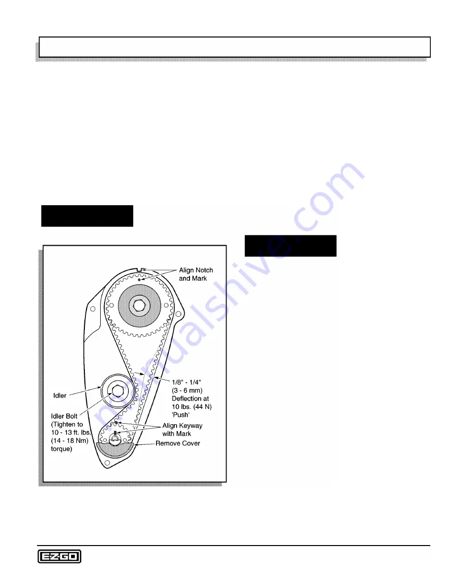
Fig. 5 Timing Belt Adjustment
At yearly intervals, the timing belt tension should be
adjusted. To do this, remove the rubber plug in the timing
cover to provide access to the idler pulley adjusting bolt
(Ref Fig. 5 on page G-5). Loosen the tensioning bolt (1/4
- 1/2 turn). Rotate the engine one full turn which will allow
the spring to apply tension to the belt. Tighten the idler
adjusting nut to 10 - 13 ft. lbs (14 - 18 Nm) torque. Spray
the rubber plug with a vinyl protective spray in order to
ease the installation of the plug.
For information relating to the replacement of the timing
belt, refer to 4 Cycle Engine Shop Rebuild and Service
Parts Manual (E-Z-GO P/N 27615-G01 ).
COMPRESSION TESTS
Tool List
Qty. Required
Compression gauge .................................................... 1
Spark plug wrench ....................................................... 1
Ratchet, 3/8" drive ....................................................... 1
.A_ WARNING.A_
section 'A'.
To
prevent inadvertent
movement of vehicle,
engage neutral lock per
Compression tests are one of the most accurate meth
ods of analyzing engine performance. To obtain maxi
mum efficiency from the fuel explosion, the combustion
chamber must be sealed. Efficiency can be affected by
problems with rings, pistons, head gaskets and valves.
Most problems associated with these components can
be detected with a cylinder compression gauge. Incorrect
use of a compression gauge can result in unnecessary
work and expenditures (Ref Fig. 6 on page G-6).
Compression gauge E-Z-GO part number 72524-G01 is
recommended.
To properly perform an accurate compression test:
1. Remove belt to clutch.
2. Remove the air filter to eliminate the possibility of a
restricted air passage.
3. A well charged good battery should be used. Weak
batteries may not allow the correct cranking speed.
4. Starter belts that drag or slip will affect the compres
sion reading.
5. Fully open the choke and accelerator baffle plate.
Should either of these baffle plates be partly closed,
the compression reading may be inaccurate and indi
cate low.
6. The engine must be at normal operating temperature
in order for the components to expand.
Repair and Service Manual
Page G-5
Summary of Contents for 4 CADDY 1999
Page 6: ...TABLE OF CONTENTS Notes __________________________ _ Page iv Repair and Service Manual...
Page 10: ...SAFETY INFORMATION Notes _________________________ _ Page viii Repair and Service Manual...
Page 26: ...SAFETY Notes _ _ ___________________________ _ Page B ii Repair and Service Manual...
Page 48: ...BODY Notes _ _ ___________________________ _ Page C ii Repair and Service Manual...
Page 56: ...WHEELS AND TIRES Notes __________________________ _ Page D ii Repair and Service Manual...
Page 72: ...SPEED CONTROL Notes _ _ ________________________ _ Page F ii Repair and Service Manual...
Page 80: ...ENGINE Notes _ _ __________________________ _ Page G ii Repair and Service Manual...
Page 94: ...FUEL SYSTEM Notes _ _ _________________________ _ Page H ii Repair and Service Manual...
Page 110: ...ELECTRICAL Notes _ _ _________________________ _ Page K ii Repair and Service Manual...
Page 120: ...ACCESSORY WIRING Notes __________________________ _ Page L ii Repair and Service Manual...
Page 148: ...REAR SUSPENSION Notes __________________________ _ Page N ii Repair and Service Manual...
Page 154: ...REAR AXLE Notes _ _ ___________________________ _ Page P ii Repair and Service Manual...
Page 158: ...PAINT Notes _ _ ___________________________ _ Page Q ii Repair and Service Manual...
Page 162: ...TROUBLESHOOTING Notes _ _ ________________________ _ Page R ii Repair and Service Manual...
Page 170: ...LIMITED WARRANTY Notes __________________________ _ Page S ii Repair and Service Manual...
Page 176: ...LIMITED WARRANTY Notes __________________________ _ Page S 6 Repair and Service Manual...
Page 178: ...GENERAL SPECIFICATIONS Notes _________________________ _ Page T ii Repair and Service Manual...


