Page 6
OPERATION AND SERVICE INFORMATION
Owner’s Guide
Read all of this manual to become thoroughly familiar with this vehicle. Pay particular attention to all Notes, Cautions and Warnings.
B
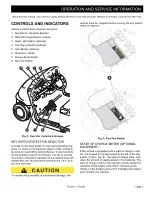
HEADLIGHT SWITCH (OPTIONAL EQUIP-
MENT)
If the vehicle is equipped with headlights, the ON/OFF
switch (3) is located on the instrument panel to the left
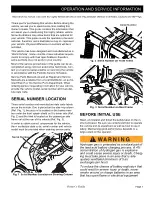
of the key switch (1) (Ref. Fig. 8).
TURN SIGNAL SWITCH (OPTIONAL EQUIP-
MENT)
If the vehicle is equipped with turn signals, the switch (4)
is mounted on the steering column (Ref. Fig. 8).
HORN (OPTIONAL EQUIPMENT)
If the vehicle is equipped with a horn, the horn button (5)
is located on the driver’s side floorboard; depressing the
button will sound the vehicle’s horn (Ref. Fig. 8).
If the vehicle is equipped with factory installed custom acces-
sories, some accessories remain operational with the key
switch in the ‘OFF’ position.
ACCELERATOR & BRAKE PEDALS
With the key switch in the ’F’ or ’R’ position, depressing
the accelerator pedal (6) starts the motor and will move
the vehicle in the direction indicated on the key switch/
direction selector. This vehicle is equipped with a motor
brake; when the accelerator pedal is released, the motor
will stop. To stop the vehicle more quickly , depress the
service brake pedal (7)(Ref. Fig. 8).
PARKING BRAKE
This vehicle is equipped with an automatic parking
brake; when the vehicle is stopped the parking brake is
automatically set. The parking brake is released when
the key switch/direction selector is in forward (’F’) or re-
verse (’R’) and the accelerator is depressed. The park-
ing brake is also released when the run/tow switch is
placed in the ’TOW’ or (on CE vehicles) position
with the key switch turned to neutral (’N’).
In the event of a controller failure the parking brake can
be released using the Manual Release Lever located
under the seat on the end of the AC motor on the driver
side of the vehicle. To use this lever, turn the key switch
to ’OFF’ then move the manual release lever in a
counter clockwise direction and hold in down while mov-
ing the vehicle. Once the handle is released the parking
brake is activated again.
Use of the manual brake release lever will
release the park brake and may cause the
vehicle to move unexpectedly.
RUN/TOW SWITCH
Before attempting to tow the vehicle, turn the key
switch to ’N’ and move the Run/Tow switch to the
‘TOW’ position. Failure to do so will damage the con-
troller or motor.
The RUN/TOW switch should always be returned to the ’RUN’
or (on CE vehicles) position after towing the vehicle. If
the switch is left in the ’TOW’ or (on CE vehicles) position
for an extended period of time it will drain the batteries.
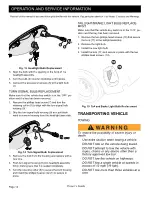
The run/tow switch (8) is located under the seat on the
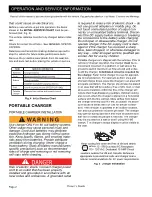
passenger side of the vehicle (Ref. Fig. 9).
With the switch in the ‘TOW’ or (on CE vehicles)
position and the key in ’N’:
•
the electronic parking brake is deactivated, which
allows the vehicle to be towed or roll freely, except
in the event of a controller failure
•
the service brake is still active
•
the reverse warning beeper is deactivated
With the switch in ‘RUN’ or (on CE vehicles) posi-
tion:
•
the electronic parking brake is deactivated and the
reverse warning beeper features are activated
OPERATING THE VEHICLE
Improper use of the vehicle or the lack of proper main-
tenance may result in damage or decreased perfor-
mance.
Read and understand the following warnings before
attempting to operate the vehicle.
To reduce the possibility of severe injury or
Summary of Contents for RXV Fleet Freedom Shuttle 2+2
Page 47: ...Page 27 Owner s Guide GENERAL SPECIFICATIONS GENERAL SPECIFICATIONS...
Page 55: ...Page 35 Owner s Guide WARRANTY LIMITED WARRANTIES...
Page 57: ...Page 37 Owner s Guide DECLARATION OF CONFORMITY DECLARATION OF CONFORMITY EUROPE ONLY...
Page 60: ...Page 40 Owner s Guide DECLARATION OF CONFORMITY...
Page 107: ...Seite 27 ALLGEMEINE TECHNISCHE DATEN ALLGEMEINE TECHNISCHE DATEN Betriebsanleitung...
Page 115: ...Seite 35 GARANTIE Betriebsanleitung BEGRENZTE GEW HRLEISTUNG...
Page 117: ...Seite 37 KONFORMIT TSERKL RUNG Betriebsanleitung KONFORMIT TSERKL RUNG NUR EUROPA...
Page 120: ...Seite 40 KONFORMIT TSERKL RUNG Betriebsanleitung...

