OPERATION AND SERVICE INFORMATION
Page 11
Owner’s Guide
Read all of this manual to become thoroughly familiar with this vehicle. Pay particular attention to all Notes, Cautions and Warnings.
B
B
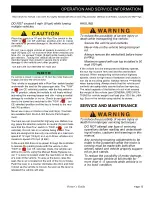
sure be higher than recommended on tire sidewall.
All
four tires
should have the same pressure for optimum
handling characteristics. Be sure to install the valve stem
dust cap after checking or inflating.
The vehicle is fitted with low pressure tubeless tires
mounted on one piece rims; therefore, the most cost
effective way to repair a puncture in the tread is to use a
commercial tire plug.
Tire plug tools and plugs are available at most automotive
parts outlets and have the advantage of not requiring the tire
be removed from the wheel.
If the tire is flat, remove the wheel and inflate the tire to
the maximum recommended pressure for the tire.
Immerse the tire in water to locate the leak and mark
with chalk. Insert tire plug in accordance with manufac-
turer’s instructions
.
To reduce the possibility of severe injury, be
sure the mounting/demounting machine is
anchored to floor. Wear OSHA approved safe-
ty equipment when mounting/demounting tires.
If the tire is to be removed or mounted, the tire changing
machine manufacturer’s recommendations must be fol-
lowed in order to reduce possibility of severe injury.
WHEEL INSTALLATION
To reduce the possibility of component damage, do not
tighten lug nuts to more than 85 ft. lbs. (115 Nm)
torque.
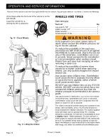
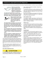
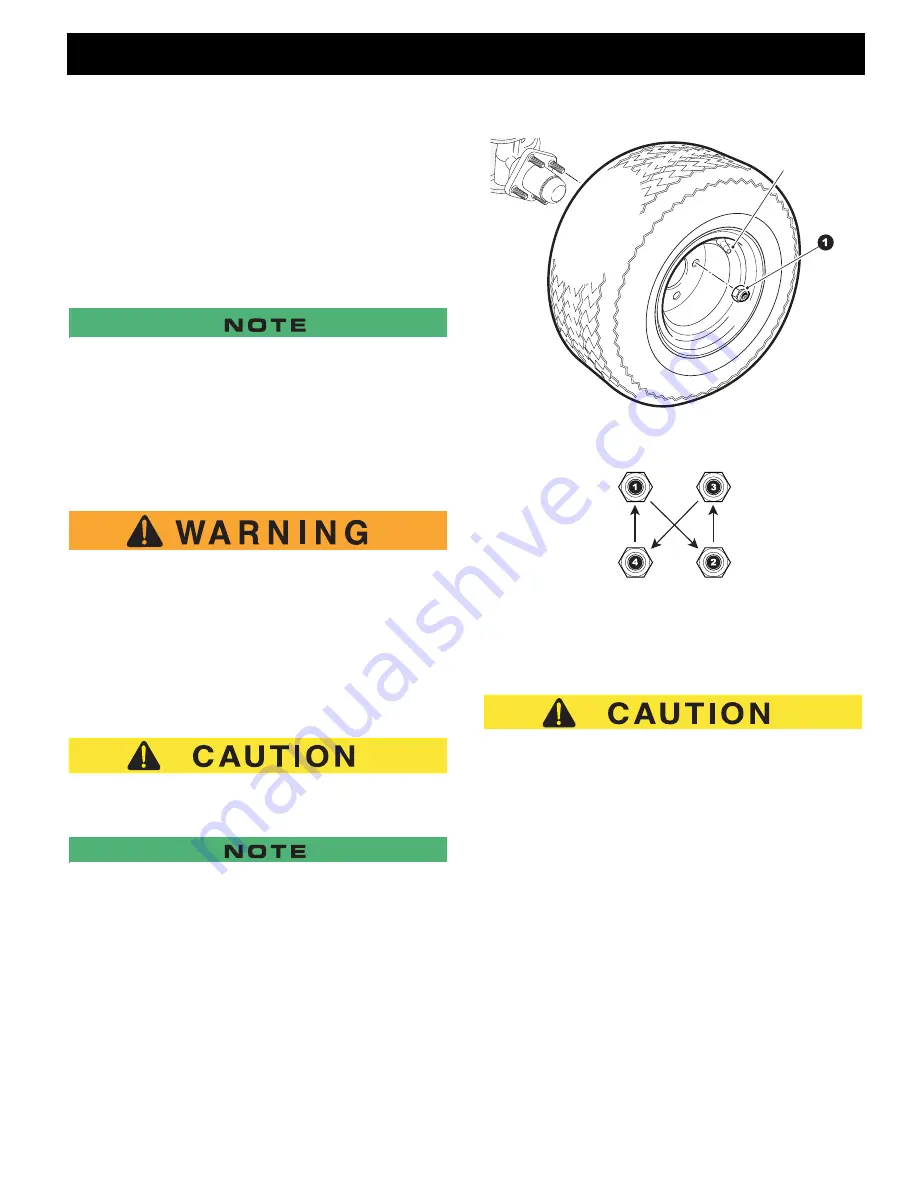
It is important to follow the ‘cross sequence’ pattern when
installing lug nuts. This will assure even seating of the wheel
against the hub.
With the valve stem to the outside, mount the wheel on-
to the hub with lug nuts. Finger tighten the lug nuts (1) in
a ‘cross sequence’ pattern (Ref. Fig. 12). Tighten the lug
nuts to 50 - 85 ft. lbs. (70 - 115 Nm) torque in 20 ft. lbs.
(30 Nm) increments following the ‘cross sequence’ pat-
tern.
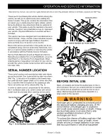
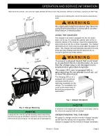
Fig. 12 Wheel Installation
LIGHT BULB REPLACEMENT
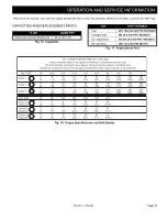
To reduce the possibility of premature bulb failure, do
not touch new bulbs with bare fingers. Use clean, dry
tissue or paper towel to handle the glass portion of the
bulb.
HEAD LIGHT BULB REPLACEMENT
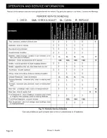
Make sure that the vehicle key switch is in the ’OFF’ po-
sition and the key has been removed. For vehicles
equipped with lights mounted in the cowl locate the
headlight bulb socket on the backside of the light as-
sembly.
1. Disconnect the accessory harness (5) from the light
bulb.
2. Turn the headlight bulb (3) clockwise and pull to re-
move.
Valve Stem Cap
Cross Sequence
Tire style may vary
Summary of Contents for RXV Fleet Freedom Shuttle 2+2
Page 47: ...Page 27 Owner s Guide GENERAL SPECIFICATIONS GENERAL SPECIFICATIONS...
Page 55: ...Page 35 Owner s Guide WARRANTY LIMITED WARRANTIES...
Page 57: ...Page 37 Owner s Guide DECLARATION OF CONFORMITY DECLARATION OF CONFORMITY EUROPE ONLY...
Page 60: ...Page 40 Owner s Guide DECLARATION OF CONFORMITY...
Page 107: ...Seite 27 ALLGEMEINE TECHNISCHE DATEN ALLGEMEINE TECHNISCHE DATEN Betriebsanleitung...
Page 115: ...Seite 35 GARANTIE Betriebsanleitung BEGRENZTE GEW HRLEISTUNG...
Page 117: ...Seite 37 KONFORMIT TSERKL RUNG Betriebsanleitung KONFORMIT TSERKL RUNG NUR EUROPA...
Page 120: ...Seite 40 KONFORMIT TSERKL RUNG Betriebsanleitung...

