ELECTRONIC SPEED CONTROL - TCT
Page E-9
Repair and Service Manual
Read all of Section B and this section before attempting any procedure. Pay particular attention to all Notices, Cautions, Dangers and Warnings.
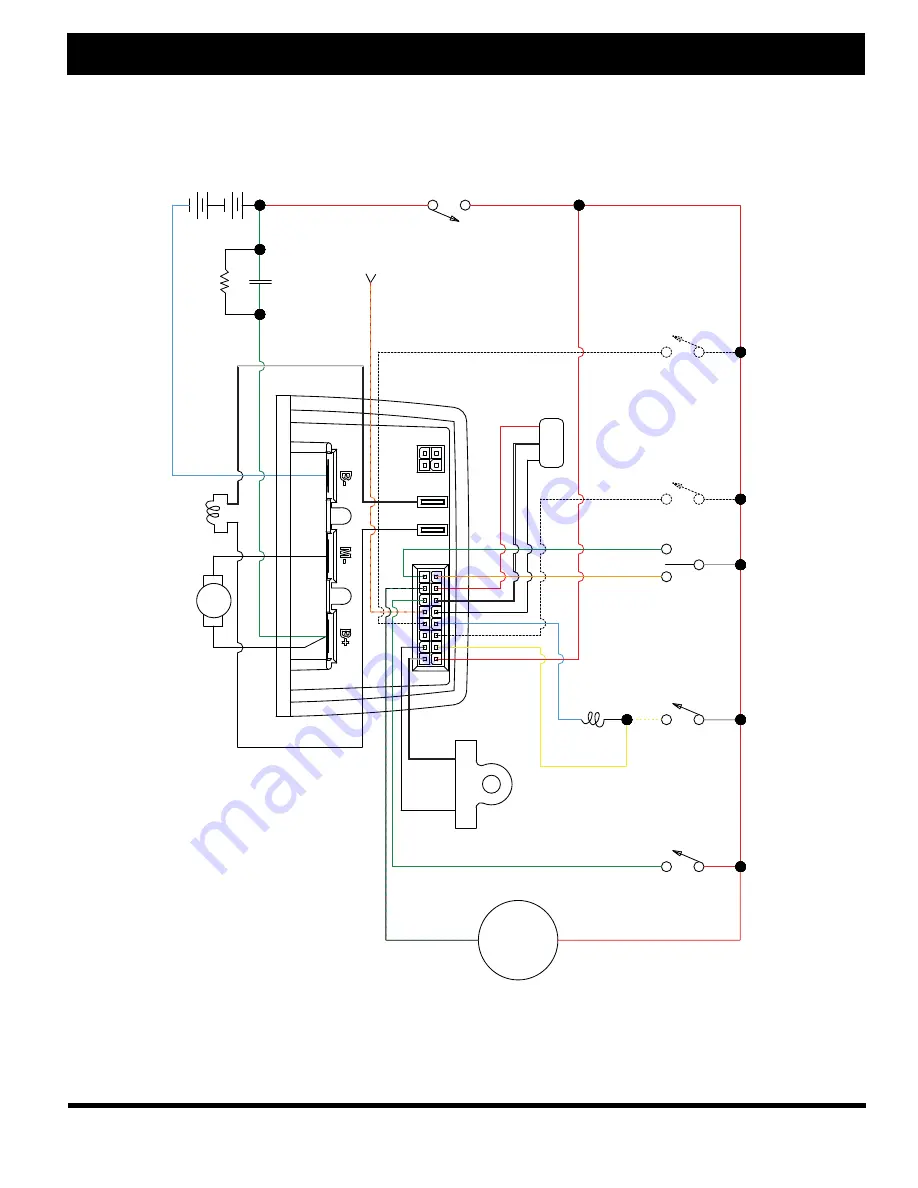
Fig. 9 Controller Wiring Diagram
KSI
WHT
WHT
WHT
YEL
BLU
MAIN
COIL
BLU
RED
RED
RED
RED
RUN /
T
OW
ORG / RED
ORG
GRN
GREY
WHT
/
YEL
WHT
RED
RED
GRN / BLK
BLK
BLK
BLK
BLK
A1
A
A2
F2
S2
S1
1
2
3
4
16
8
9
1
F1
BLK
GRN
ITS
GRN
B-
B+
BA
TTER
Y
48V
MAIN
CONT
ACT
OR
PRECHARGE
RESIST
OR
GRN
PEDAL
PERSONALITY
SELECT
PERSONALITY
SELECT
REVERSE
BUZZER
SPEED
SENSOR
CHARGE
DISABLE
+
-
+
-


