Page F-2
SPEED CONTROL
Repair and Service Manual
Read all of Section B and this section before attempting any procedure. Pay particular attention to all Notices, Cautions, Warnings and Dangers.
Governor Operation
Until the vehicle reaches its governed speed, the vehicle
will continue to accelerate in relation to the accelerator
pedal position. When the governed speed is reached,
the ground speed governor in the rear axle assembly
operates against the governor spring and closes the car-
buretor until the correct governed speed is achieved
(Ref Fig. 1).
It is the force of the governor spring in response to
accelerator pedal and governor arm position which con-
trols the position of the carburetor throttle plate. This
spring cushions sudden changes in throttle linkage posi-
tion to provide smooth power transmission.
Driving above governed speed could cause a
loss of vehicle control and possible injury or
death.
Tampering with or adjusting the governor or other speed
control components will void the warranty.
TROUBLESHOOTING
Erratic acceleration and performance that does
not
include a notable increase in governed speed, may indi-
cate the need for a linkage adjustment.
Symptoms that include an increase in governed speed
indicate:
•
a possible governor failure within the rear axle
•
worn components in the governor system
•
improper adjustment of linkage system
Other factors may effect the performance characteristics of the
vehicle but they should be investigated only after confirming
the linkage adjustment.
SPEED CONTROL
Tool List
Qty.
Phillips Screwdriver ..................................................... 1
Flat Blade Screwdriver ................................................ 1
Needle Nose Pliers...................................................... 1
Slip Joint Pliers ............................................................ 1
Open End Wrench, 10 mm"......................................... 2
Ratchet ........................................................................ 1
Socket, 15 mm............................................................. 1
Torque Wrench, in. lbs................................................. 1
Torque Wrench, ft. lbs.................................................. 1
Drill, 1/4" ...................................................................... 1
Drill bit, 3/16"................................................................1
Rivet gun......................................................................1
Remove the negative (-) battery cable at the
battery to prevent the vehicle moving and the
possible personal injury that may result. Refer
to section ‘B’ of this manual for additional cau-
tions and warnings.
Be sure to follow the sequence indicated when making linkage
adjustments.
Accelerator Cable Removal at Governor
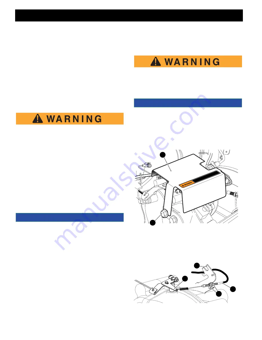
Remove the governor cover (2) by drilling out the rivet
securing the cover on the passenger side and loosening
the hex head bolt (3) on the driver side of the vehicle.
Fig. 2 Governor Cover Removal
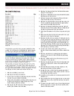
To remove the accelerator cable (9) from the governor,
loosen the nuts (13) securing the cable to the accelera-
tor cable bracket (14) at the rear axle and unhook the
spring from the upper governor lever (15).
Fig. 3 Accelerator Cable at Governor
NOTICE
NOTICE
DO NOT
TAMPER W
TH OR
ATTEMPT
TO CHANGE
THE
AD
USTMENT
OF
THE
DO NOT
TAMPER
W TH OR
ATTEMPT
TO CHANGE
THE
AD
USTMENT
OF
THE
GOVERNOR. GOVERNOR
TAMPERING CAN RESUL
T N SERIOUS PERSONAL
GOVERNOR
. GOVERNOR
TAMPERING CAN RES
ULT
N SERIOUS PERSON
AL
NJUR
Y AND W
LL VOID
THE VEHICLE W
ARRANTY
.
NJUR
Y AND W
LL VOID
THE VEHICL
E W
ARRANTY
.
3
2
14
15
9
13


