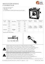
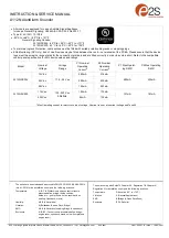
INSTRUCTION & SERVICE MANUAL
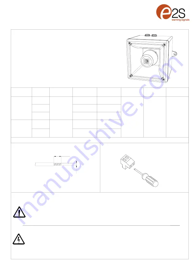
A112N AlertAlarm Sounder
E2S Warning Signals Impress House, Mansell Road, Acton, London W3 7QH sales@e2s.com e2s.com D221
-
00
-
001
-
IS Issue 1 10/05/2021
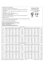
Unit Type
Code
Nominal
Voltage
Voltage Range
Nominal Current*
P1
Nominal Current*
P2
Nominal SPL
P1 / P2
Max SPL
P1 / P2
Average SPL
P1 / P2
A112NDC024
12 Vdc
11.5
-
54Vdc
280mA
376mA
113.7dB(A) /
116.6dB(A)
Tone 44 @ 1m
115dB(A) /
118.4dB(A)
Tone 4 @ 1m
110.8dB(A) /
114.8dB(A)
All Tones @
1m
24 Vdc
225mA
430mA
48 Vdc
122mA
223mA
A112NAC230
115 Vac
100mA
173mA
100
-
240Vac
50/60Hz
230 Vac
65mA
105mA
*Nominal current at nominal voltage
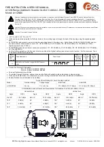
•
-
40°C to +66°C (104°F to 151°F)
•
Type 4 / 4X / 3R / 13, IP66
•
1.8Kg (3.96lb)
•
CE, A112NXDC024 & A112NXDC048 CPR compliant, All units UL Listed
0.4Nm
5mm
0.5 2.5mm
Attention
: Installation must be carried out by an electrician in compliance with the latest codes and regulations.
Attention
: L'installation doit être effectuée par un électricien conformément aux derniers codes et réglementations.
Achtung
: Die Installation muss von einem Elektriker gemäß den neuesten Vorschriften und Bestimmungen durchgeführt werden.
Attenzione
: L'installazione deve essere eseguita da un elettricista in conformità con i codici e le normative più recenti.
Atención
: La instalación debe ser realizada por un electricista de acuerdo con los últimos códigos y regulaciones.
Atenção:
A instalação deve ser realizada por um eletricista de acordo com os códigos e regulamentos mais recentes.
Внимание
:
установка должна выполняться электриком в соответствии с последними нормами и правилами
.
Attention
: Disconnect from power source before installation or service to prevent electric shock
Attention
: Débranchez
-
le de la source d'alimentation avant l'installation ou l'entretien pour éviter tout choc électrique.
Achtung
: Vor Installation oder Wartung von der Stromquelle trennen, um einen Stromschlag zu vermeiden.
Attenzione
: scollegare dall'alimentazione prima dell'installazione o dell'assistenza per evitare scosse elettriche.
Atención
: desconéctelo de la fuente de alimentación antes de la instalación o el servicio para evitar descargas eléctricas.
Atenção:
Desconecte da fonte de alimentação antes da instalação ou serviço para evitar choque elétrico
Внимание
:
отключите от источника питания перед установкой или обслуживанием
,
чтобы предотвратить поражение электрическим током
.
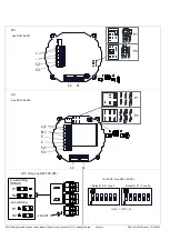
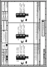
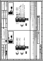
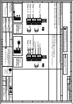
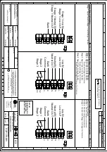
AC: 1.0 –
2.5mm
2
/ AWG18 –
AWG12
DC: 0.2 –
2.5mm
2
/ AWG24 –
AWG12
Summary of Contents for A112N
Page 12: ...Page left Intentionally blank ...


